Pinpoint Test E: A Single Illumination Source Is Inoperative - Steering Wheel Control Switches
- E1 CHECK VOLTAGE AT THE CLOCKSPRING LOWER CONNECTOR
- Remove the driver air bag module. Refer to SUPPLEMENTAL RESTRAINT SYSTEM
.
- Disconnect: Clockspring Lower Connector C218b.
- Connect the restraint system diagnostic tool 418-F403 (2 req'd) to the driver air bag electrical connectors.
- Connect the battery. Refer to BATTERY, MOUNTING AND CABLES
.
- Place the headlamp switch in the parking lamps ON position.
- Increase the instrument panel dim control switch to maximum brightness level.
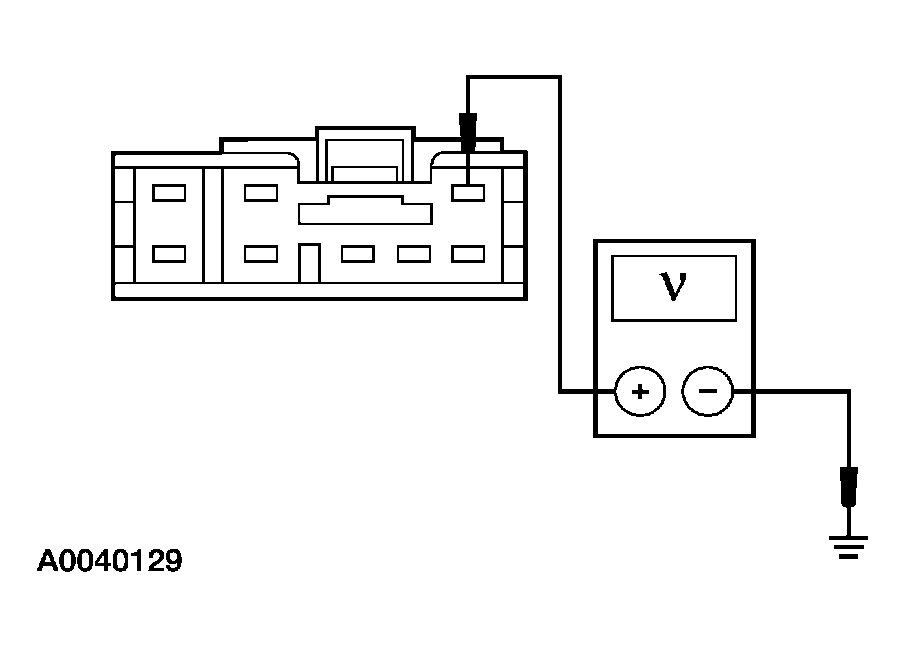
- Measure the voltage between the clockspring lower C218b pin 3, circuit 1045 (DB/WH), harness side and ground.
 Courtesy of FORD MOTOR CO.
- Is the voltage greater than 10 volts?
- E2 CHECK GROUND AT THE CLOCKSPRING LOWER CONNECTOR
- Place the headlamp switch in the parking lamps OFF position.
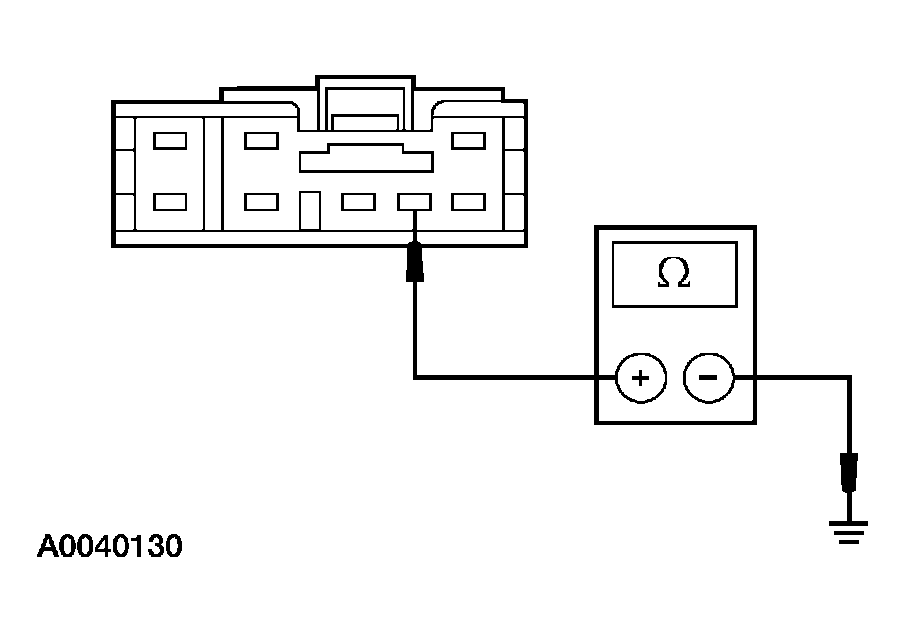
- Measure the resistance between the steering wheel control switch C218b pin 7, circuit 57 (BK), harness side and ground.
 Courtesy of FORD MOTOR CO.
- Is the resistance less than 5 ohms?
- E3 CHECK VOLTAGE AT THE UPPER CLOCKSPRING CONNECTOR
- Connect: Clockspring Lower Connector C218b.
- Disconnect: Clockspring Upper Harness Connector.
- Place the headlamp switch in the parking lamps ON position.
- Increase the instrument panel dim control switch to maximum brightness level.
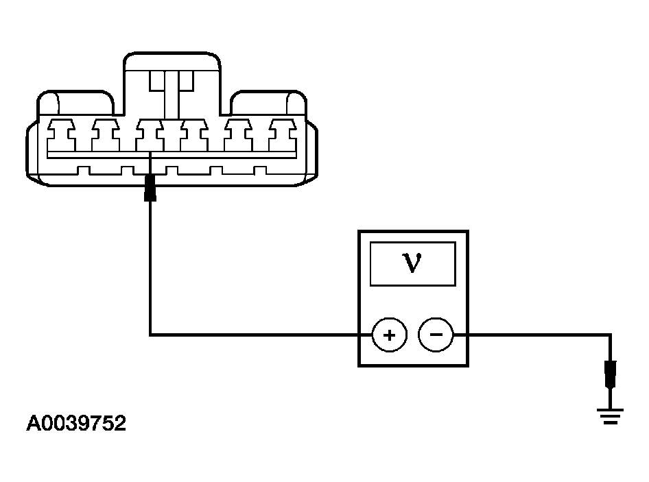
- Measure the voltage between the upper clockspring connector pin 3, circuit 1045 (DB/WH), component side and ground.
 Courtesy of FORD MOTOR CO.
- Is the voltage greater than 10 volts?
- E4 CHECK GROUND AT THE UPPER CLOCKSPRING CONNECTOR
- Place the headlamp switch in the parking lamps OFF position.
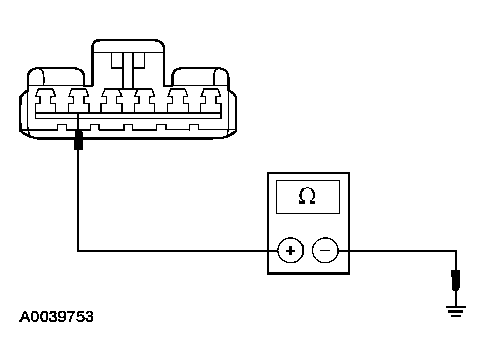
- Measure the resistance between the upper clockspring connector pin 2, circuit 57 (BK), component side and ground.
 Courtesy of FORD MOTOR CO.
- Is the resistance less than 5 ohms?