Test A: Instrument Cluster Inoperative
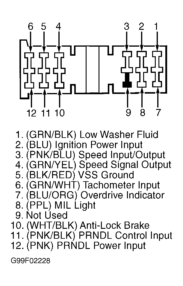
- Turn ignition switch to LOCK position. Disconnect negative battery cable. Remove instrument cluster. See INSTRUMENT CLUSTER under REMOVAL & INSTALLATION. Disconnect instrument cluster harness connectors. Reconnect negative battery cable and turn ignition switch to RUN position. Measure voltage between ground and terminal No. 9 (Blue wire) at instrument cluster harness connector C266a. Measure voltage between ground and terminal No. 2 (Blue wire) at instrument cluster harness connector C266b. Measure voltage between ground and terminal No. 5 (Blue wire) at instrument cluster harness connector C266c. See Fig 1-Fig 3
. If battery voltage exists in all measurements, go to next step. If battery voltage does not exist in all measurements, repair open or short to ground in Blue wire between fuse junction panel and instrument cluster.
- Turn ignition switch to LOCK position. Measure resistance between ground and terminal No. 6 (Black wire) at instrument cluster harness connector C266a and terminal No. 5 (Black/Red wire) at harness connector C266b. If resistance in both measurements is 5 ohms or less, replace instrument cluster printed circuit and retest. See PRINTED CIRCUIT under REMOVAL & INSTALLATION. If resistance in either measurement is greater than 5 ohms, repair open or high resistance in circuit(s) in question and retest system.
 Courtesy of FORD MOTOR CO.
 Courtesy of FORD MOTOR CO.
 Courtesy of FORD MOTOR CO.