Test A: Instrument Cluster Inoperative
- Turn ignition off. Disconnect negative battery cable. Remove instrument cluster. See ELECTRONIC INSTRUMENT CLUSTER under REMOVAL & INSTALLATION. Disconnect instrument cluster connectors. Reconnect negative battery cable and turn ignition on. Measure voltage between ground and instrument cluster connector C267B terminal No. 3 (Blue wire). Measure voltage between ground and instrument cluster connector C267A terminal No. 5 (Violet wire). Measure voltage between ground and instrument cluster connector C267C terminal No. 20 (Blue wire). See Fig 1-Fig 3
. If voltage measurements are more than 10 volts, go to next step. If any voltage measurement is 10 volts or less, repair open in Blue or Violet wire between interior fuse panel and instrument cluster.
- Turn ignition off. Measure resistance between ground and instrument cluster connector C267B terminals No. 4 (Black/Red wire) and No. 6 (Black wire). Measure resistance between ground and instrument cluster connector C267C terminal No. 19 (Black wire). If resistances are less than 5 ohms, replace instrument cluster and retest. See ELECTRONIC INSTRUMENT CLUSTER under REMOVAL & INSTALLATION. If any resistance is more than 5 ohms, repair open in appropriate wire. See WIRING DIAGRAMS .
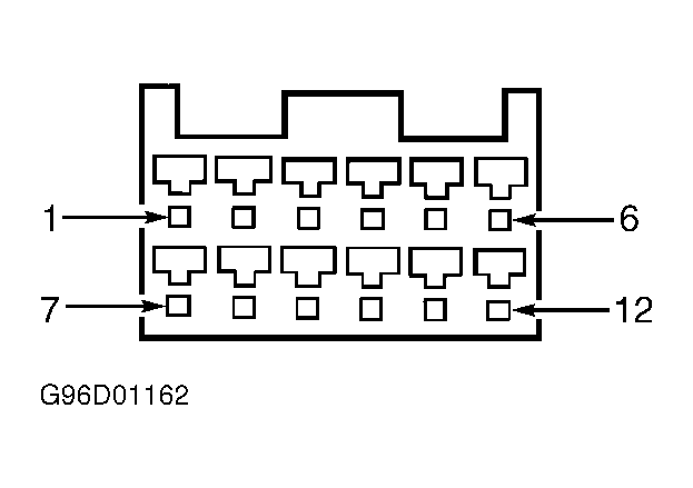 Courtesy of FORD MOTOR CO.
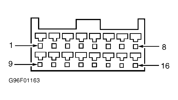 Courtesy of FORD MOTOR CO.
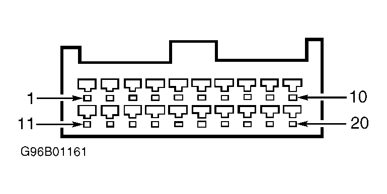 Courtesy of FORD MOTOR CO.