Test G: Brake Warning Light Never On
- Turn ignition switch off. Remove instrument cluster. See INSTRUMENT CLUSTER in REMOVAL & INSTALLATION. Remove brake warning light bulb and check continuity of bulb. If bulb is okay, go to next step. If bulb is bad, replace bulb and retest system.
- Disconnect all instrument cluster connectors. Turn ignition on. Using voltmeter, measure voltage between instrument cluster connector C266C terminal No. 10 (Yellow/Purple wire) and instrument cluster connector C266B terminal No. 2 (Blue wire). See Figure and Figure
. If voltage is more than 10 volts, replace printed circuit. See PRINTED CIRCUIT under REMOVAL & INSTALLATION. If voltage is 10 volts or less, go to next step.
- Turn ignition off. Disconnect brake fluid level switch 2-pin connector at brake fluid reservoir. Remove BULB CHECK relay from engine compartment fuse/relay panel. Remove joint connector located behind top right side of instrument cluster. Remove top shorting strip. Measure resistance of Yellow/Purple wire between instrument cluster connector C266C terminal No. 10 and joint connector C2011 terminal No. 10. See Fig 1. Measure resistance of Yellow/Purple wire between BULB CHECK relay connector and instrument cluster connector C266C terminal No. 10. Measure resistance of Yellow/Purple wire between brake fluid level switch connector and instrument cluster connector C266C terminal No. 10. If resistance in any measurement is more than 5 ohms, repair open in appropriate Yellow/Purple wire. Retest system. If resistance in all measurements are less than 5 ohms, go to next step.
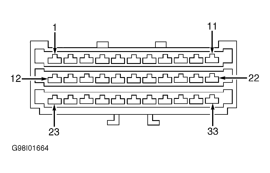 Courtesy of FORD MOTOR CO.
- Ensure ignition is off. Connect jumper wire between battery voltage and BULB CHECK relay terminal No. 1. Measure resistances between BULB CHECK relay terminals No. 3 and No. 5. See Fig 2. Ground BULB CHECK relay terminal No. 2. If resistance between BULB CHECK relay terminals No. 3 and No. 5 is less than 5 ohms with ground connected and more than 10 k/ohms with ground disconnected, go to next step. If resistance between BULB CHECK relay terminals No. 3 and 5 is 5 ohms or more with ground connected or 10 k/ohms or less with ground disconnected, replace BULB CHECK relay.
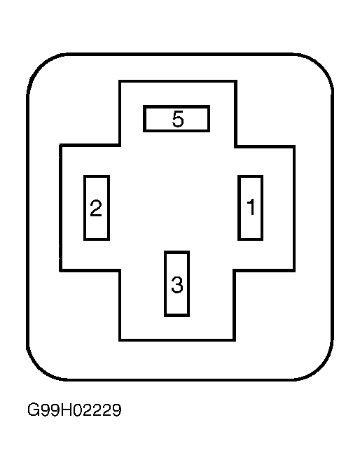 Courtesy of FORD MOTOR CO.
- Turn ignition on. Measure voltage between ground and BULB CHECK relay connector terminal No. 1 (Blue wire). If voltage is more than 10 volts, go to next step. If voltage is 10 volts or less, repair open in Blue wire between BULB CHECK relay and interior fuse panel.
- Turn ignition off. Measure resistance of Blue/Yellow wire between BULB CHECK relay connector terminal No. 2 and joint connector C2011 terminal No. 6. See Fig 1 and Fig 2
. If resistance is more than 5 ohms, go to next step. If resistance is less than 5 ohms, repair open Blue/Yellow wire. Retest system.
- Measure resistance between ground and brake fluid level switch connector Black wire. If resistance is less than 5 ohms, go to next step. If resistance is 5 ohms or more, repair open Black wire. Retest system.
- Ensure ignition is off and brake fluid level switch 2-pin connector at brake fluid reservoir is disconnected. Remove screen inside brake fluid reservoir. Depress brake fluid reservoir float with a clean screwdriver. Measure resistance between brake fluid level switch terminals. If resistance is less than 5 ohms with float depressed and more than 10 k/ohms with float released, go to next step. If resistance is 5 ohms or more with float depressed or 10 k/ohms or less with float released, replace brake fluid level switch.
- Ensure ignition is off. Disconnect parking brake switch connector. Measure resistance of Green/Black wire between parking brake switch connector and joint connector C2011 terminal No. 9. If resistance is less than 5 ohms, go to next step. If resistance is more than 5 ohms, repair open Green/Black wire. Retest system.
- Ensure parking brake switch is disconnected. Set parking brake. Measure resistance between ground and parking brake switch terminal component side. If resistance is less than 5 ohms, go to next step. If resistance is 5 ohms or more, replace parking brake switch.
- Measure resistance between joint connector C2011 (top shorting strip) terminals as follows: Ensure polarity is correct, shorting strip is a diode shorting strip.
- Terminal No. 6 (+) and No. 5 (-).
- Terminal No. 2 (+) and No. 5 (-).
- Terminal No. 10 (+) and No. 9 (-).
- Terminal No. 10 (+) and No. 8 (-).
If resistance in all measurements is less than 5 ohms, go to TEST H: CHARGE INDICATOR NEVER ON . If resistance in any measurement is 5 ohms or more, replace top diode shorting strip on joint connector C2011. Retest system.