Test A: Display Not Illuminated, Too Dim Or Blank But Backlighted
- Inspect the ELECTRON (10-amp) fuse and RELAYS (10-amp) fuse located in the interior fuse panel. If fuses are blown, go to next step. If fuses are okay, go to step 5).
- Turn ignition off. Replace blown fuse. Turn ignition on. Inspect fuse again. If fuses are okay, go to step 5). If the ELECTRON fuse is blown, go to step 4). If the RELAYS fuse is blown, go to next step.
- Ensure ignition is off. Remove RELAYS fuse. Remove instrument cluster. See REMOVAL & INSTALLATION
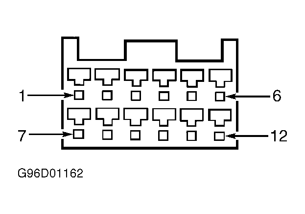
. Disconnect instrument cluster connector C274. See Fig 1
. Measure resistance between ground and right terminal of RELAYS fuse holder. If resistance is less than 5 ohms, repair short to ground in Blue wire. If resistance is 5 ohms or more, replace fuse and go to step 5).
 Courtesy of FORD MOTOR CO.
- Ensure ignition is off. Remove ELECTRON fuse. Remove instrument cluster. See REMOVAL & INSTALLATION
. Disconnect instrument cluster connector C272. See Fig 1
. Measure resistance between ground and right terminal of RELAYS fuse holder. If resistance is less than 5 ohms, repair snort to ground in Purple wire. If resistance is 5 ohms or more, replace fuse and go to next step.
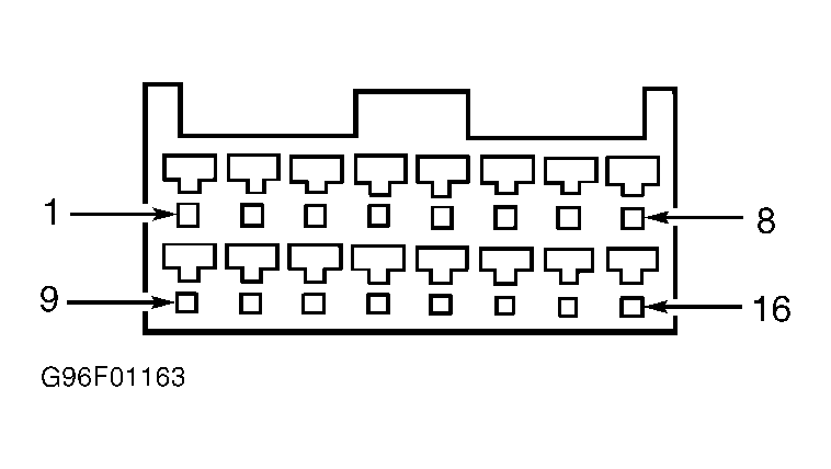
- Ensure ignition is off. With instrument cluster removed, disconnect all connectors. Turn ignition on. Measure voltage between ground and instrument cluster connector C274, pin No. 3 (Blue wire). Measure voltage between ground and instrument cluster connector C272, pin No. 5 (Purple wire). See Fig 1
and Fig 2
. If voltage is 10 volts or more, go to next step. If voltage is less than 10 volts, repair open in Blue or Purple wire.
 Courtesy of FORD MOTOR CO.
- Turn ignition off. Remove RELAYS fuse. Measure resistance between ground and instrument cluster connector C274, pin No. 6 (Black wire). See Fig 1
. If resistance is less than 5 ohms, replace instrument cluster. If resistance is 5 ohms or more, go to next step.
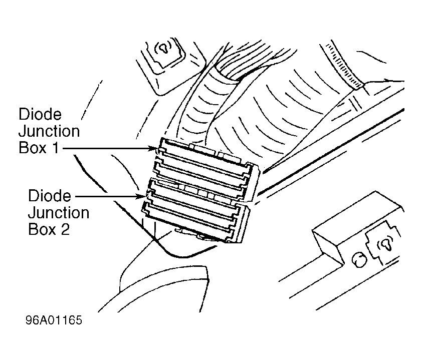
- Leave ignition off. Disconnect diode junction box 2 connector. See Fig 3
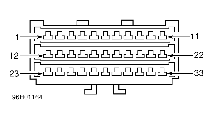
. With instrument cluster connector C274 disconnected, measure resistance between connector C274, pin No. 6 (Black wire) and diode junction box 2 connector C2010, pin No. 32 (Black wire). See Fig 1
and Fig 4
. If resistance is less than 5 ohms, go to next step. If resistance is 5 ohms or more, repair open in Black wire.
 Courtesy of FORD MOTOR CO.
 Courtesy of FORD MOTOR CO.
- Leave ignition off. Measure resistance between ground and diode junction box 2 connector C2010, pin No. 33 (Black wire). See Fig 4
. If resistance is less than 5 ohms, replace gray diode strip. If resistance is 5 ohms or more, repair open in Black wire.