Instrument Panel: Installation
- Position the instrument panel to the vehicle.
- Install the instrument panel upper bolts and tighten to specification. See TORQUE SPECIFICATION
.
- Install the instrument panel center nut, see Fig 1
. Tighten the instrument panel center nut to specification. See TORQUE SPECIFICATION
.
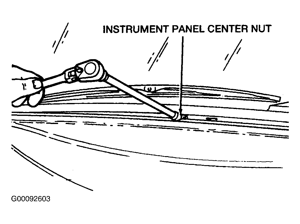 Courtesy of FORD MOTOR CO.
- Connect the two head-lamp dimmer sensor control electrical connectors and position the head-lamp dimmer sensor control to the instrument panel, if equipped.
- Install the two head-lamp dimmer sensor control screws and tighten, if equipped. See Figure
.
- Connect the light sensor amplifier electrical connector, if equipped. See Figure
.
- Install the light sensor amplifier, if equipped.
- Install the instrument panel upper molding.
- Install the windshield side garnish moldings. See Figure
.
- Install the console bin to the radio chassis bracket. Install and tighten the four console bin screws.
- Install the radio chassis. See RADIO CHASSIS & TAPE PLAYER
.
- Connect the five climate control assembly electrical connectors.
- Install the climate control assembly.
- Install the four climate control assembly screws and tighten. See Figure
.
- Install the instrument panel ash receptacle. See ASH RECEPTACLE
.
- Install the center instrument panel finish panel and center instrument panel finish panel screw and tighten to specification. See TORQUE SPECIFICATION
. See Figure
.
- Connect the power outside rear view mirror control electrical connector and install the outside rear view mirror control switch, if equipped.
- Position the safety belt warning chime and install the two safety belt warning chime bracket screws. Tighten the safety belt warning chime bracket screws.
- Connect the safety belt warning chime electrical connector.
- Install the instrument cluster. See INSTRUMENT CLUSTER
.
- Install the steering column.
- Connect the glove compartment lamp electrical connector.
- Install the glove compartment and the two glove compartment screws. Tighten the glove compartment screws to specification. See TORQUE SPECIFICATION
.
- Install the right hand and left hand instrument panel screws and tighten to specification. See TORQUE SPECIFICATION
. See Figure
.
- Install the right hand inner duct screw. See Figure
.
- Install the left hand instrument panel reinforcement. Install the four left hand instrument panel reinforcement bolts. Tighten the left hand instrument panel reinforcement bolts to specification. See TORQUE SPECIFICATION
. See Figure
.
- Install the instrument panel steering column cover, the four instrument panel steering column cover screws and the plastic rivet.
- Install the plastic rivet, the four instrument panel lower cover screws and the instrument panel lower cover. See Figure
.
- Install the right hand inner instrument panel lower cover, the two right hand inner instrument panel lower cover screws and the plastic nut. Tighten the right hand inner instrument panel lower cover screws to specification. See TORQUE SPECIFICATION
. Connect the foot lamp electrical connector, if equipped.
- Install the left hand inner instrument panel lower cover, the two left hand inner instrument panel lower cover screws and the plastic nut. Tighten the left hand inner instrument panel lower cover screws to specification. See TORQUE SPECIFICATION
. Connect the foot lamp electrical connector, if equipped. See Figure
.
- Install the console compartment door and the four plastic console compartment door screws.
- Connect the battery ground cable.