Instrument Panel Support: Removal
- Remove the instrument panel. See INSTRUMENT PANEL
.
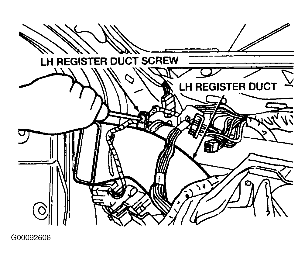
- Remove the left hand register duct screw and the left hand register duct. See Fig 1
.
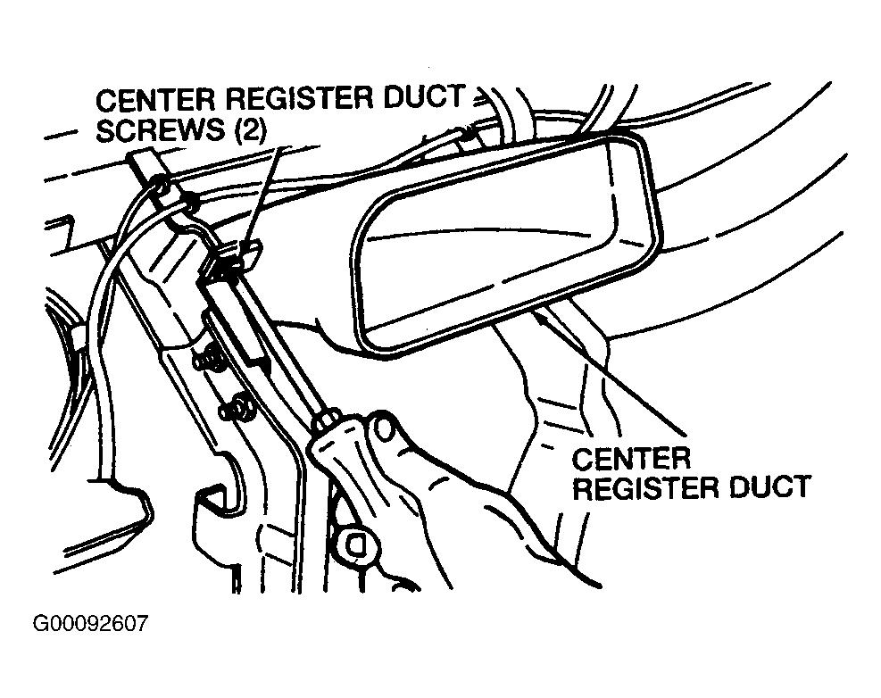
- Remove the two center duct screws and the center duct. See Fig 2
.
 Courtesy of FORD MOTOR CO.
 Courtesy of FORD MOTOR CO.
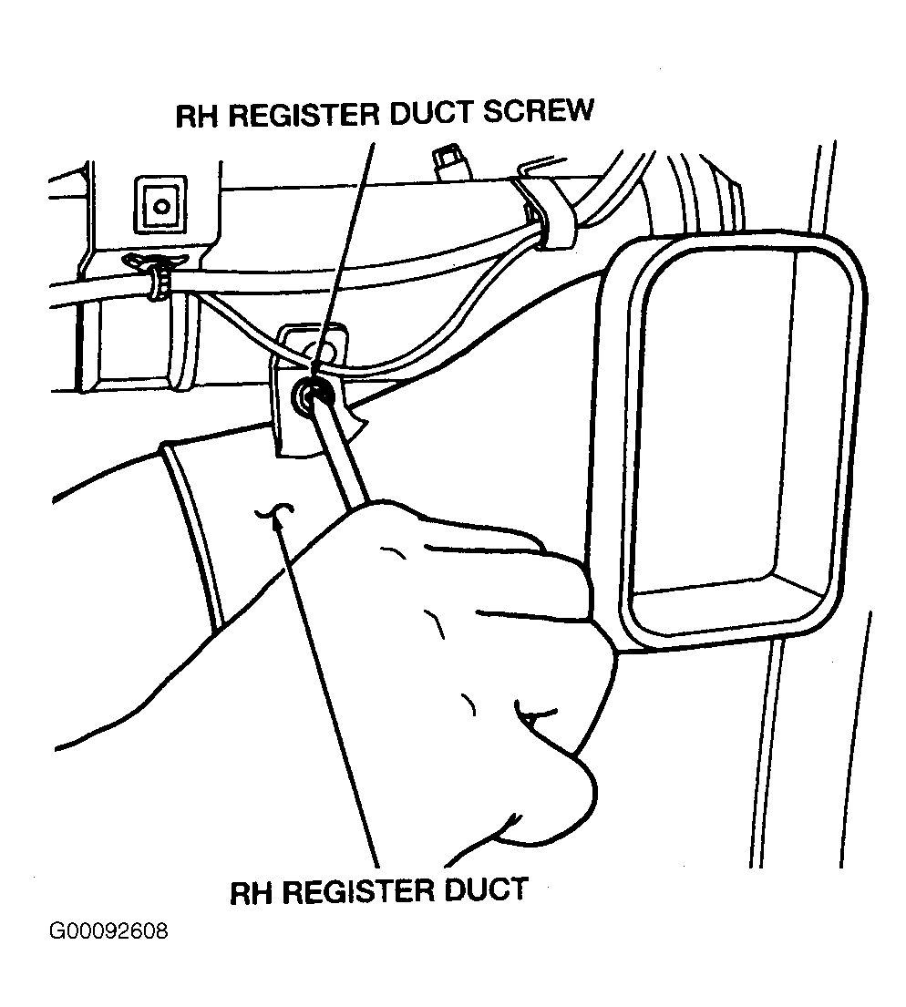
- Remove the right hand register duct screw and the right hand register duct. See Fig 3
.
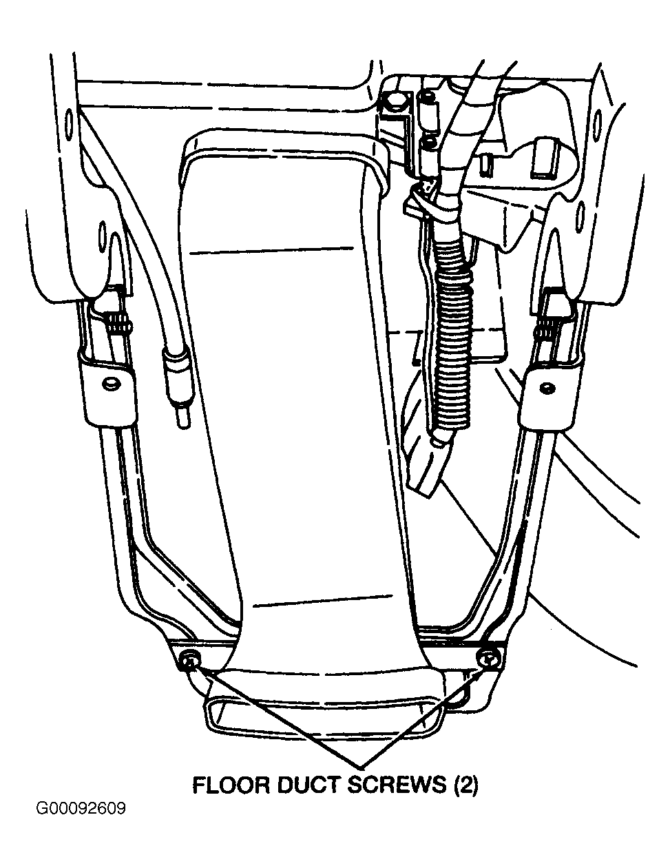
- Remove the two heater outlet floor duct screws and the heater outlet floor duct. See Fig 4
.
 Courtesy of FORD MOTOR CO.
 Courtesy of FORD MOTOR CO.
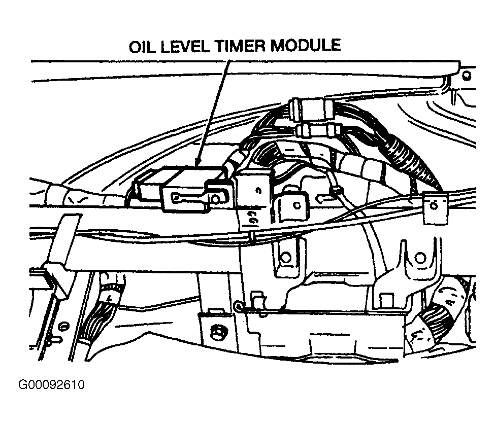
- Remove the low oil level timer module from its bracket. See Fig 5
.
 Courtesy of FORD MOTOR CO.
- Separate the electrical harness from the instrument panel support.
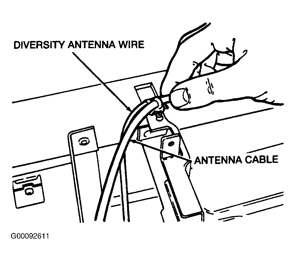
- Separate the radio antenna lead in cable from the instrument panel support. See Fig 6
.
- Remove the two ground bolts and the ground wires from the instrument panel bracket
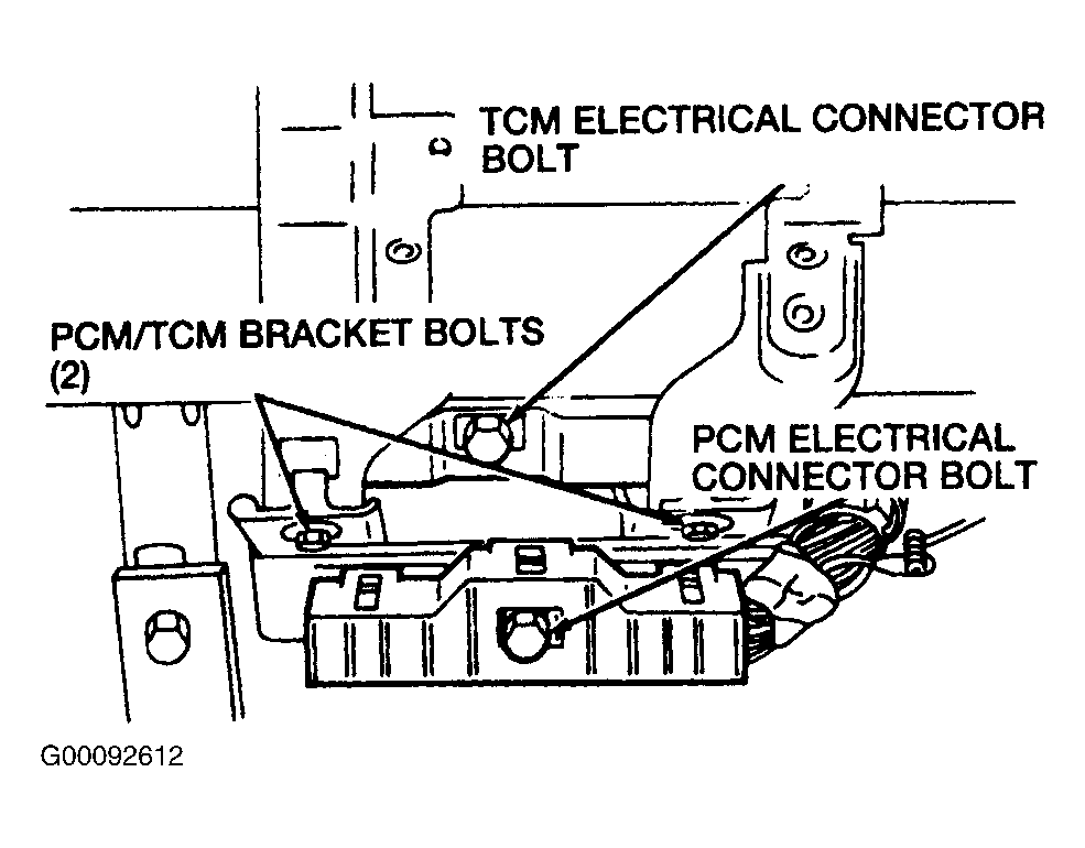
- Loosen the Powertrain Control Module (PCM) electrical connector bolt and disconnect the PCM electrical connector. See Fig 7
.
 Courtesy of FORD MOTOR CO.
 Courtesy of FORD MOTOR CO.
- Loosen the Transmission Control Module (TCM) electrical connector bolt and disconnect the TCM electrical connector.
- Remove the two PCM bolts and remove the PCM and the TCM.
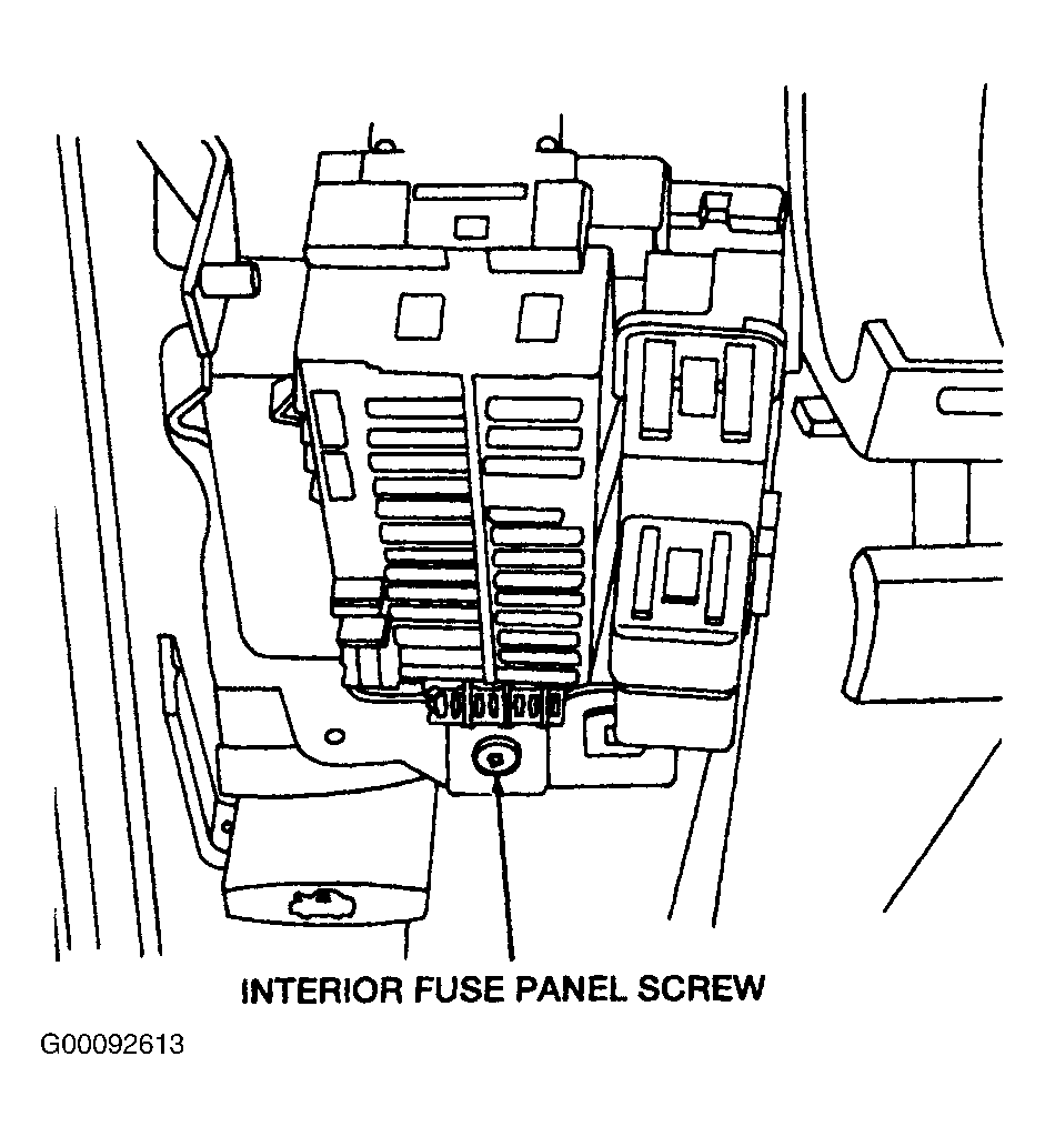
- Remove the interior fuse junction panel screw. See Fig 8
.
- Remove the two parking brake release cable screws.
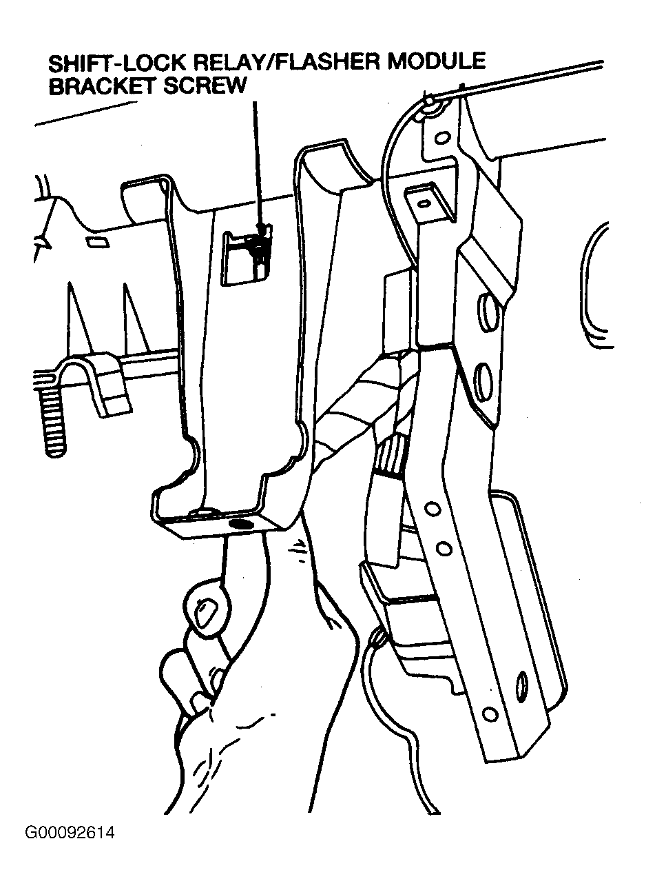
- Remove the shift lock relay/indicator flasher module bracket screw. See Fig 9
.
 Courtesy of FORD MOTOR CO.
 Courtesy of FORD MOTOR CO.
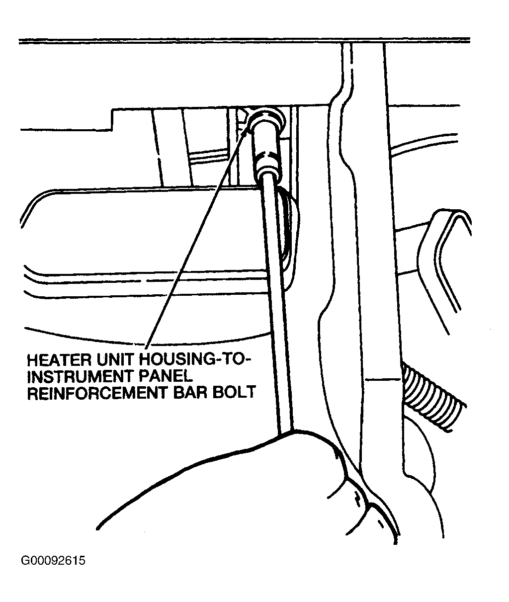
- Remove the heater unit housing-to-instrument panel support bolt. See Fig 10
.
 Courtesy of FORD MOTOR CO.
- Separate the harness from the instrument panel bracket.
- Remove the anti-lock brake control module bracket screw.
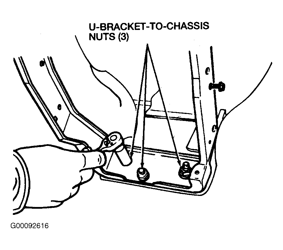
- Remove the three instrument panel bracket-to-chassis nuts. See Fig 11
.
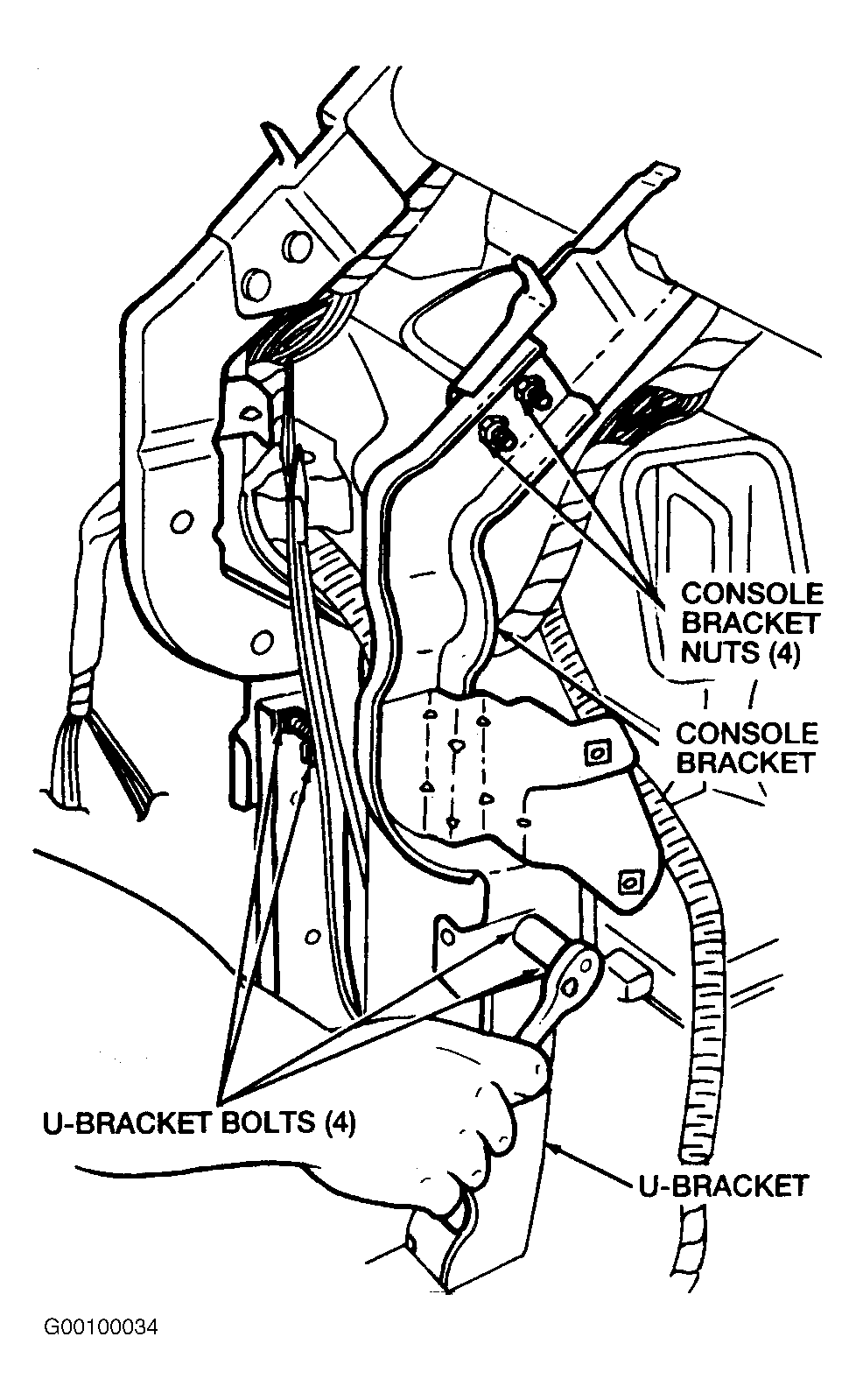
- Remove the four instrument panel bracket bolts and remove the instrument panel bracket. See Fig 12
.
- Remove the two left hand and the two right hand instrument panel lower bracket bolts and the instrument panel lower brackets.
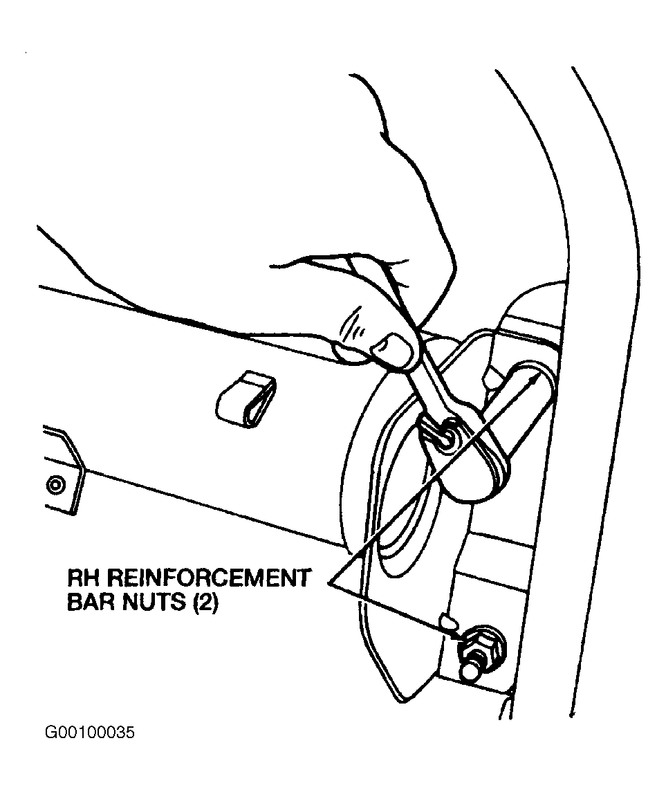
- Remove the two right hand instrument panel support nuts. See Fig 13
.
 Courtesy of FORD MOTOR CO.
 Courtesy of FORD MOTOR CO.
 Courtesy of FORD MOTOR CO.
- Remove the two left hand instrument panel support bolts and the two nuts.
- Remove the four instrument panel support upper bolts. See Figure
.
- Remove the instrument panel support from the vehicle.