Instrument Panel Support: Installation
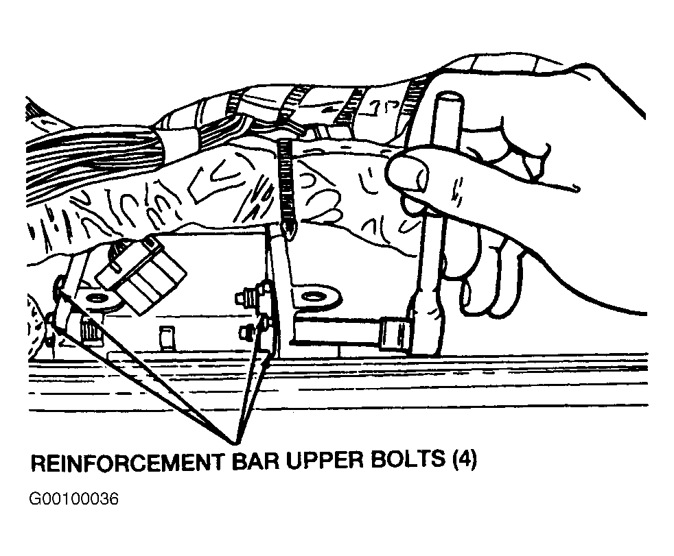
- Install the instrument panel support. Install the four instrument panel support upper bolts and tighten to specification. See TORQUE SPECIFICATION
. See Fig 1
.
 Courtesy of FORD MOTOR CO.
- Install the two left hand and right hand instrument panel support nuts and tighten to specification. See TORQUE SPECIFICATION
. See Figure
.
- Install the two instrument panel lower brackets, the two left hand and the two right hand instrument panel lower bracket nuts. Tighten the instrument panel lower bracket nuts to specification. See TORQUE SPECIFICATION
.
- Install the instrument panel bracket and the four instrument panel bracket bolts. Tighten the instrument panel bracket bolts to specification. See TORQUE SPECIFICATION
. See Figure
.
- Install the three instrument panel bracket-to-chassis nuts. Tighten the instrument panel bracket-to-chassis nuts to specification. See TORQUE SPECIFICATION
. See Figure
.
- Install the anti-lock brake control module bracket screw.
- Attach the harness to the instrument panel bracket.
- Install the heater unit housing-to-instrument panel support bolt. See Figure
.
- Install the shift lock relay/indicator flasher module bracket screw. See Figure
.
- Install the two parking brake release cable screws.
- Install the interior fuse junction panel screw. See Figure
.
- Position the Powertrain Control Module (PCM), the Transmission Control Module (TCM), and the bracket to the instrument panel support and install the PCM bolts.
- Connect the TCM electrical connector and tighten the TCM electrical connector bolt until the red projection appears.
- Connect the PCM electrical connector and tighten the PCM electrical connector bolt until the red projection appears. See Figure
.
- Position the ground wires to the instrument panel bracket and install the ground bolts.
- Attach the radio antenna lead in cable to the instrument panel support. See Figure
.
- Attach the electrical harness to the instrument panel support.
- Attach the low oil level relay to its bracket. See Figure
.
- Install the heater outlet floor duct and the two heater outlet floor duct screws. See Figure
.
- Install the right hand register duct and the right hand register duct screw. See Figure
.
- Install the center duct and the two center duct screws. See Figure
.
- Install the left hand register duct and the left hand register duct screw. See Figure
.
- Install the instrument panel. Refer to the procedure in this section.