Pinion Assembly, Bearings, Rack & Housing: Reassembly
- Install lower bearing in pocket at bottom of housing. On front wheel drive models, coat the entire length of rack with grease. Install rack in housing.
- With rack moved to right stop, install pinion shaft. Make sure pinion shaft end is engaged in lower bearing inside diameter. Install upper bearing.
- On rear wheel drive models, install shims, spacer, gasket, pinion cover and bolts. Adjust bearing preload.
- On front wheel drive models, turn pinion from lock to lock, counting the number of turns. Turn pinion back from lock half the total number of turns. The flat on pinion gear must at 3 o'clock as viewed from driver's position. If pinion is incorrectly oriented, remove pinion gear and re-engage gear teeth to correct.
- Install shims, spacer, gasket, pinion cover and bolts. Center pinion cover and check bearing preload. Adjust if necessary. Install new pinion seal in cover.
- On all models, install right ball housing/tie rod assembly on end of rack. Install support yoke, spring, shims, gaskets, yoke cover and bolts. Adjust yoke preload.
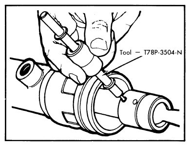 Courtesy of FORD MOTOR CO.
NOTE:
Make sure rack is restrained with an adjustable wrench during tightening to prevent damage to pinion teeth.
TIGHTENING SPECIFICATIONS
| Application |
Ft. Lbs. (N.m) |
| Front Wheel Drive Models |
| |
Pinion Cover Bolts |
12-18 (16-24) |
| |
Steering Gear Mounting Bolts |
48-55 (65-75) |
| |
Tie Rod-to-Spindle Nut |
27-32 (37-43) |
| |
Tie Rod Jam Nut |
42-50 (57-68) |
| |
Flex Coupling Bolt |
20-37 (27-50) |
| |
Ball Housing-to-Rack |
40-51 (54-69) |
| |
Support Yoke Cover Bolts |
60-96 INCH Lbs. (7-11) |
| Rear Wheel Drive Models |
| |
Support Yoke Cover Bolts |
15-22 (20-30) |
| |
Pinion Cover Bolts |
15-22 (20-30) |
| |
Steering Gear Mounting Bolts |
90-100 (122-136) |
| |
Tie Rod-to-Spindle Nut |
41-47 (56-64) |
| |
Tie Rod Jam Nut |
41-50 (56-68) |
| |
Flex Coupling Bolt |
20-37 (27-50) |
| |
Ball Housing-to-Rack |
45-60 (61-81) |