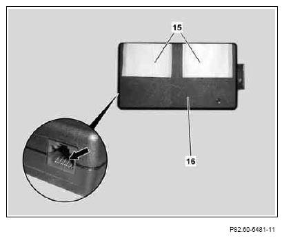
- Glue two of the Velcro strips (15) included in installation set to iPod interface (16) as per picture.
 The small connecting socket (see arrow in enlarged detail) must be at the bottom left. The surfaces to be glued must be dry and free of grease and dust.
- Affix the other two Velcro strips to the Velcro strips on the iPod interface (16).
 Courtesy of MERCEDES-BENZ USA
 Courtesy of MERCEDES-BENZ USA
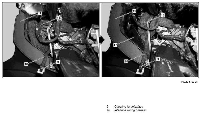
- Reposition damping material (18) behind right side piece (19) of center console as per picture in such a way that no damping material (18) remains on the surface (17).
 It must be ensured that no components are damaged or the functionality thereof impaired by the repositioning of the damping material (18).
 Courtesy of MERCEDES-BENZ USA
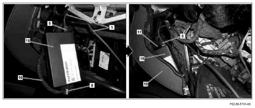
- Connect interface coupling (5) of iPod wiring harness (1) and interface coupling (9) of interface wiring harness (10) to iPod interface (16).
The excess length of the iPod wiring harness (1) must be strapped down to the wiring harnesses in the vehicle later, when the glove box is installed.
- Slide iPod interface (16) behind right side piece (19) of center console as per picture and stick to surface (17) using Velcro strips attached to iPod interface (16).
The surfaces to be glued must be dry and free of grease and dust.
Risk of breakage!
Do not kink fiber optic cable and do not route over sharp edges or bend in radii smaller than 25 mm. Tensile forces on inserts must not exceed 65 N. Do not squeeze fiber optic cable and do not compress with clamps or cable ties.
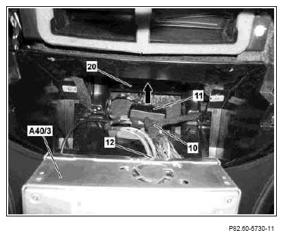
- Connect COMMAND adapter coupling (12) of interface wiring harness (10) to COMMAND controller unit (A40/3).
- Slide COMMAND adapter plug (11) of interface wiring harness (10) between housing (20) and center tunnel in direction of arrow.
COMMAND adapter plug (11) of interface wiring harness (10) must be secured with self-adhesive felt between housing (20) and center tunnel after the COMMAND controller unit (A40/3) has been installed.
 Courtesy of MERCEDES-BENZ USA