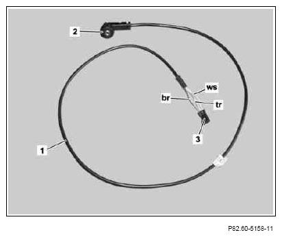
- Release black 3-pin coupling (3) from wiring harness for audio AUX jack (1).
- Unplug white line (ws), brown line (br) and transparent line (tr) from black 3-pin coupling (3).
 The black 3-pin coupling (3) is no longer needed.
 Courtesy of MERCEDES-BENZ USA
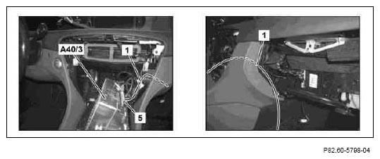
- Route wiring harness for audio AUX jack (1) in instrument panel as per picture.
- Disconnect black 22-pin coupling (5) of COMMAND controller unit (A40/3).
 Courtesy of MERCEDES-BENZ USA
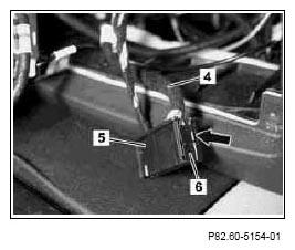
- Unlock lock (see arrow) on side of coupling (5) and pull black 20-pin contact carrier (6) of vehicle's own wiring harness (4) from coupling (5).
 Courtesy of MERCEDES-BENZ USA
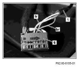
- Insert transparent line (tr) from audio AUX jack wiring harness (1) into contact cavity 6 of black 20-pin contact carrier (6).
- Insert brown line (br) from audio AUX jack wiring harness (1) into contact cavity 5 of black 20-pin contact carrier (6).
 Courtesy of MERCEDES-BENZ USA
- Insert white line (ws) of audio AUX jack wiring harness (1) into contact cavity 15 of black 20-pin contact carrier (6).
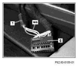 Courtesy of MERCEDES-BENZ USA
- Pull off soundproofing material (7) in the area of the hole (9) to be made in glove compartment (8).
- Drill hole (9) with a diameter of 18.5 mm in glove compartment (8) according to dimensions.
The diameter must not be larger than 18.5 mm.
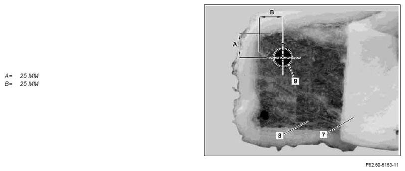 Courtesy of MERCEDES-BENZ USA
- Unclip cage (11) using a narrow flat tip screwdriver (10) at audio AUX jack (2).
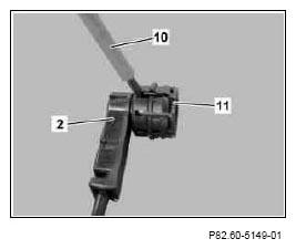 Courtesy of MERCEDES-BENZ USA
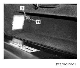
- Install audio AUX jack (2) in glove box (8) and glue on soundproofing (7).
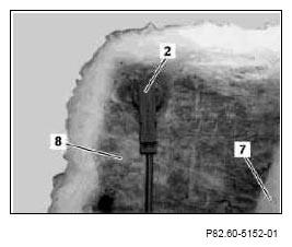 Courtesy of MERCEDES-BENZ USA
- Counterhold audio AUX jack (2) from rear and clip cage (11) to audio AUX jack (2).
Cage (11) is mechanically encoded and can only be installed in one position (groove and tongue).
 Courtesy of MERCEDES-BENZ USA