- Wrap video signal line (11) with felt tape.
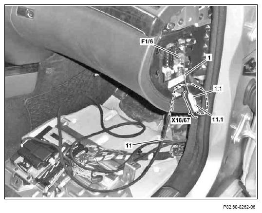
- Route white 1-pin connector (11.1) of video signal line (11) from front passenger footwell to white 1-pin coupling (1.1) of previously installed media interface wiring harness (1).
- Connect white, 1-pin connector (11.1) to white, 1-pin coupling (1.1) to form the media interface connector 1 (X18/67).
 Courtesy of MERCEDES-BENZ USA
- Route media interface connector 1 (X18/67) behind the right fuse box on the instrument panel (F1/6).
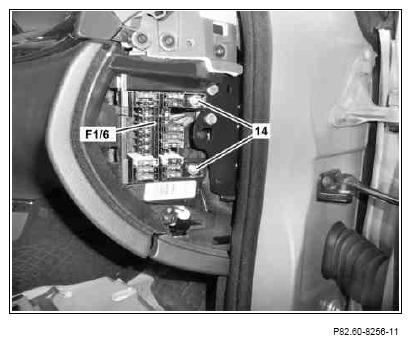
- Position fuse box of right instrument panel (F1/6) and tighten with bolts (14).
 Courtesy of MERCEDES-BENZ USA
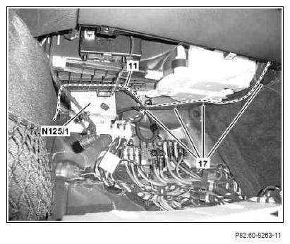
- Route video signal line (11) along media interface wiring harness to media interface control unit (N125/1) and fix in place with cable tie (17).
 Courtesy of MERCEDES-BENZ USA
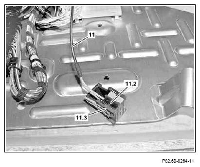
- Remove black 20-pin contact carrier (11.2) from black 40-pin coupling (11.3) of video signal line (11).
 The black 40-pin coupling (11.3) is no longer required.
 Courtesy of MERCEDES-BENZ USA
- Fold right front floor covering (18) to side in area of transmission tunnel.
- Route video signal line (11), as shown, into the COMAND controller unit slot.
Route video signal line (11) behind hose (19). The video signal line (11) must be routed 200 mm out of the COMAND controller unit slot.
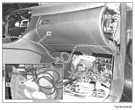 Courtesy of MERCEDES-BENZ USA
- Form a loop with video signal line (11), as shown, and fix in place with cable tie (20) behind right front floor covering (18).
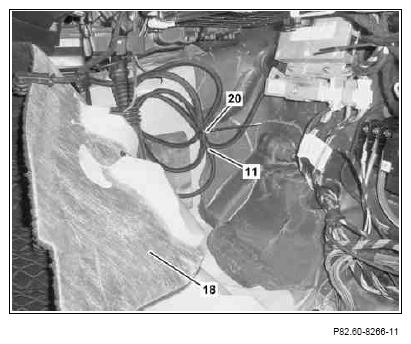 Courtesy of MERCEDES-BENZ USA
- Remove transparent line (tr) of video signal line (11) from contact cavity 33 of black 20-pin contact carrier (11.2).
- Remove screened line (sc) of video signal line (11) from contact cavity 22 of black 20-pin contact carrier (11.2).
The black 20-pin contact carrier (11.2) is no longer required.
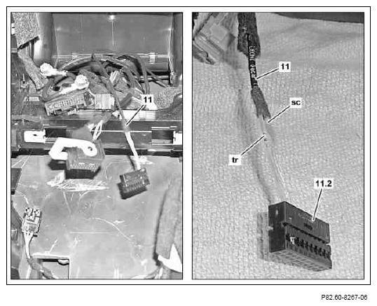 Courtesy of MERCEDES-BENZ USA
- Remove black 20-pin contact carrier (21.2) from black 40-pin coupling (21.1) of vehicle wiring harness (21).
- Install transparent line (tr) of video signal line (11) in contact cavity 33 of black 20-pin contact carrier (21.2).
- Install screened line (sc) of video signal line (11) in contact cavity 22 of black 20-pin contact carrier (21.2).
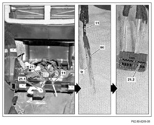 Courtesy of MERCEDES-BENZ USA
- Install black 20-pin contact carrier (21.2) in black 40-pin coupling (21.1) of vehicle wiring harness (21).
- Fix video signal line (11) in place at vehicle wiring harness (21) using cable tie.