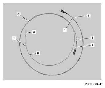
- Remove all identification labels (1) from fiber optical cable modules (8, 9) of the MOST wiring harness ordered (6).
- Remove protective cap (3) from fiber optical cable module (8).
 Protective cap (3) is no longer required.
 Courtesy of MERCEDES-BENZ USA
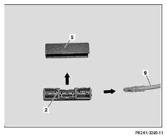
- Unclip cover (5) from adapter connector (2) in direction of arrow.
- Unlock locking tab and remove fiber optical cable module (9) from adapter connector (2).
Cover (5) and adapter connector (2) are no longer required.
 Courtesy of MERCEDES-BENZ USA
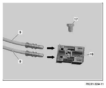
- Unclip blue retaining clip (17) from black, 2-pin MOST connector ordered (19).
- Clip fiber optical cable module (8) into chamber 1 (input) of black, 2-pin MOST connector (19).
Fiber optical cable module (8) has to be assigned to black, 2-pin MOST connector (18) in output (chamber 2) and to black, 2-pin MOST connector (19) in input (chamber 1). The fiber optical cable module (8) should catch audibly.
- Clip fiber optical cable module (9) into chamber 2 (output) of black, 2-pin MOST connector (19).
Fiber optical cable module (9) has to be assigned to black, 2-pin MOST connector (18) in input (chamber 1) and to black, 2-pin MOST connector (19) in output (chamber 2). The fiber optical cable module (9) should catch audibly.
- Clip blue retaining clip (17) into black, 2-pin MOST connector (19).
 Courtesy of MERCEDES-BENZ USA
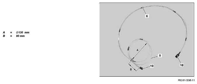
- Tie excess length of fiber optical cable module (8) and of MOST wiring harness (6) as per dimensioning in a loop to MOST (6).
Black, 2-pin MOST connector (18) will be connected later to the radio.
 Courtesy of MERCEDES-BENZ USA
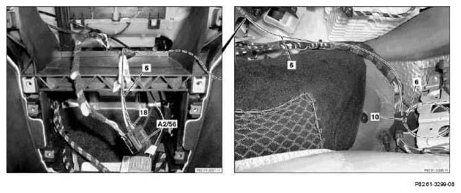 Courtesy of MERCEDES-BENZ USA
- Route black, 2-pin MOST connector (18) of MOST wiring harness (6) from right footwell into radio recess.
- Install black, 2-pin MOST connector (18) into black, 6-pin connector of radio and navigation unit (A2/56).
Black, 2-pin MOST connector (18) should catch audibly. Black, 6-pin connector will be connected later to the radio and navigation unit (A2/56).
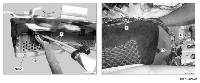 Courtesy of MERCEDES-BENZ USA
- Clip black, 2-pin MOST connector (19) of MOST wiring harness (6) into black, 6-pin MOST connector of audio gateway control unit (N93/1).
Black, 2-pin MOST connector (19) should catch audibly.
- Place loop of MOST wiring harness (6) as per the picture on left next to audio gateway control unit (N93/1).
- Route MOST wiring harness (6) along existing lines of center tunnel and footwell and fix into position.
- Attach MOST wiring harness (6) with felt tape (10) at existing lines.
 Risk of breakage!
Do not kink fiber optical cable, route over sharp edges or bend in radii smaller than 25 mm. Tensile forces on inserts must not exceed 65 N. Do not crush fiber optic cable, and do not compress with clamps or tie straps.
Risk of breakage!
Do not kink fiber optical cable, route over sharp edges or bend in radii smaller than 25 mm. Tensile forces on inserts must not exceed 65 N. Do not crush fiber optic cable, and do not compress with clamps or tie straps.