Separate rear fender - AR63.50-P-1400-02SX
 Courtesy of MERCEDES-BENZ USA
 Courtesy of MERCEDES-BENZ USA
 Courtesy of MERCEDES-BENZ USA
 COMMERCIALLY AVAILABLE TOOLS
| Number |
Designation |
| WH58.30-Z-1002-01A |
Ball cutter, dia. 12 mm |
| WH58.30-Z-1006-01A |
Vario Drill WS 91 spot weld removing tool |
| WH58.30-Z-1010-02A |
Sheet metal crimping shears |
| WH58.30-Z-1001-03A |
Round wire brush, braided, dia. 70 mm |
| WH58.30-Z-1024-04A |
Abrasive disk, dia. 115 mm, 80 m/s (max. 13, 250 RPM) |
| WH58.30-Z-1004-20A |
Hot-air gun |
| WH58.30-Z-1001-35A |
Aluminum workshop vehicle |
WORKSHOP EQUIPMENT
| WE58.40-Z-1001-03A |
Drill (electric/pneumatic) |
| WE58.40-Z-1003-03A |
Angle grinder (electric/pneumatic) |
| WE58.40-Z-1004-03A |
Body saw (electric/pneumatic) |
| WE58.40-Z-1005-03A |
Wet/dry vacuum cleaner |
REPAIR MATERIALS
| Number |
Designation |
Order number |
| BR00.45-Z-1001-07A |
Zinc dust paint suitable for spot welding |
A 000 986 34 42 |
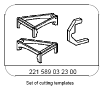
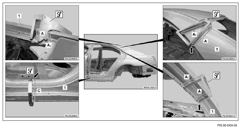
- 1.1 Scribe separation line on rear fender (1) with
 cutting template (area A).
 Courtesy of MERCEDES-BENZ USA
 Position cutting template on Y-marking. Expose Y-marking if necessary (arrow).
- 1.2 If C-pillar is damaged, use separation line on rear fender (1) (area A1).
- 2 Scribe separation line on rear fender (1) with
cutting template (area C).
Position cutting template on Y-marking. Expose Y-marking if necessary (arrow).
- 3.1 Cut rear fender (1) along separation line with body saw (area A).
 Do not damage C-pillar below (area A).
- 3.2 If C-pillar is damaged, cut separation line on rear fender (1) with body saw (area A 1).
- 4 Cut rear fender (1) along separation line with body saw (area C).
Do not damage outer side longitudinal member below (area C).
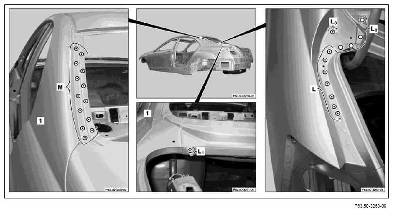
- 5 Expose spot welds on rear fender (1) (areas L, L1
, L3
and M).
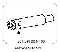
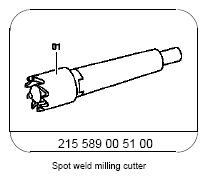
- 6 Cut out spot welds on rear fender (1) using
spot weld milling cutter or
 Vario Drill spot weld removing tool (areas L, L1
, L3
and M).
Vario Drill spot weld removing tool (areas L, L1
, L3
and M).
- 7 Expose stamping rivet on rear fender (1) (area L 2).
 Courtesy of MERCEDES-BENZ USA
- 8 Drill stamping rivet on rear fender (1) with dia. 6.5 mm drill bit (area L2).
Use rivet remover if available, to eliminate having to drill new rivet holes.
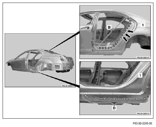
- 9 Expose spot welds on rear fender (1) (areas B and D).
- 10 Cut out spot welds on rear fender (1) using
spot weld milling cutter or
Vario Drill spot weld removing tool (areas B and D).
Cut out spot welds on rear fender (1) through two sheet metal layers (arrows).
 Courtesy of MERCEDES-BENZ USA
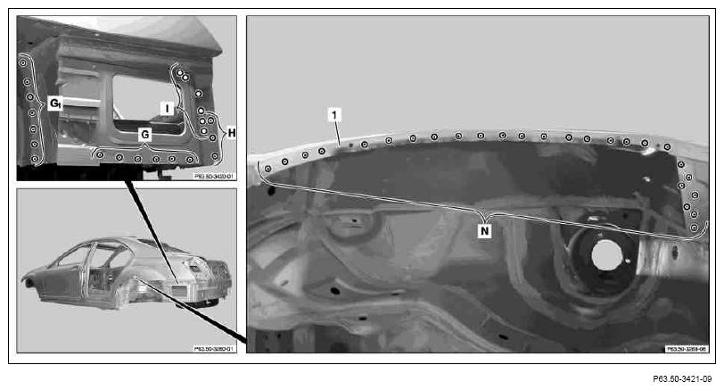
- 11 Expose spot welds on rear fender (1) (areas G1
and N).
- 12 Cut out spot welds on rear fender (1) using
spot weld milling cutter or
Vario Drill spot weld removing tool (areas G 1 and N).
- 13 Expose stamping rivets and clinch connections on rear fender (1) (areas G, H and I).
 Courtesy of MERCEDES-BENZ USA
- 14 Cut out stamping rivet on rear fender (1) with
spot weld milling cutter or
Vario Drill spot weld removing tool (areas G and H).
Use rivet remover if available, to eliminate having to drill new rivet holes.
- 15 Drill dia. 6.5 mm clinch connections in rear fender (1) (area I).
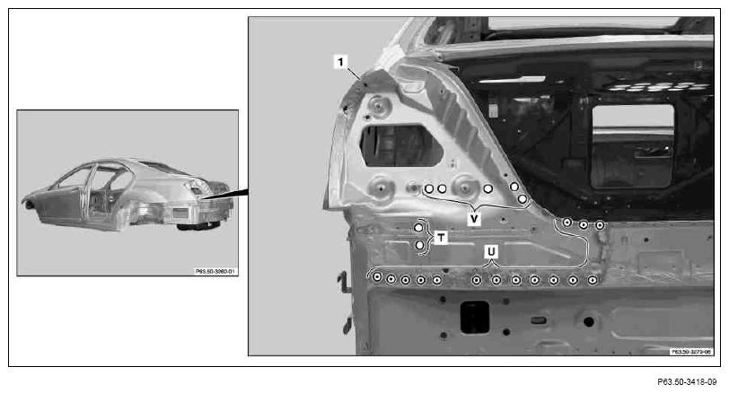
- 16 Expose stamping rivet and clinch connections on rear fender (1) (area U).
- 17 Cut out stamping rivet on rear fender (1) with
spot weld milling cutter or
Vario Drill spot weld removing tool (area U).
 Courtesy of MERCEDES-BENZ USA
Use rivet remover if available, to eliminate having to drill new rivet holes.
- 18 Drill dia. 6.5 mm clinch connections in rear fender (1) (areas T and V).
- 19 Heat rear fender (1) in cross-hatched areas using
hot air gun.
Cross-hatched areas are foamed and bonded.
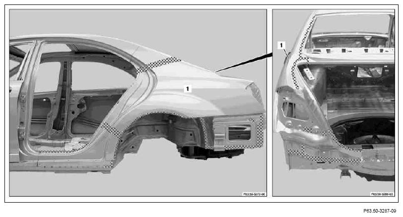 Courtesy of MERCEDES-BENZ USA
Damaged foam parts must be removed and replaced.
- 20 Remove damaged rear fender (1)
- 21 Remove adhesive residues in shaded areas using
stainless steel round brush (areas P and P 1).
- 22 Grind adhesive residues down to bare metal in cross-hatched areas using
round wire brush (areas B1
, D1
, K and K1
).
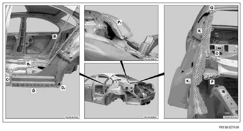 Courtesy of MERCEDES-BENZ USA
- 23 Grind mating surfaces down to bare metal in cross-hatched areas using
round wire brush (areas B, C, D, O and Q).
Grind spot weld flanges down to bare metal on both sides.
Observe pretreatment of bonding surfaces.
- 24 Coat insides of spot weld flange and riveted joints with zinc dust paint (areas B and D).
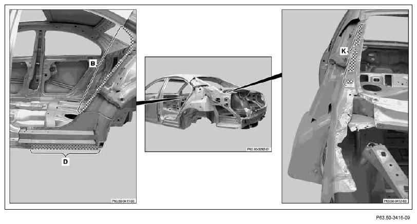 Courtesy of MERCEDES-BENZ USA
To prevent adhesion problems, do not coat bonding surfaces with zinc dust paint. (area K).
- 25 Cut rear fender (1) to size in area of upper C-pillar (arrows) with body saw
- 26 Crimp rear fender (1) in area of C-pillar (arrows) with sheet metal crimping pliers to inside.
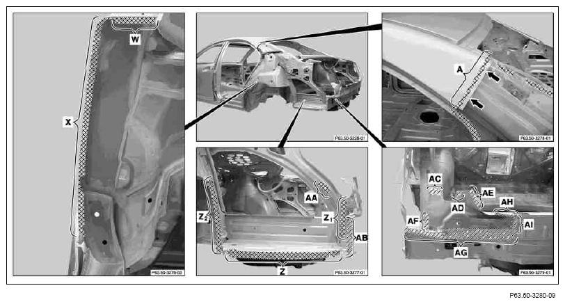 Courtesy of MERCEDES-BENZ USA
- 27 Grind mating surfaces down to bare metal in cross-hatched areas using
round wire brush (areas A, W, X, Z, Z1
, Z2
and AA).
- 28 Grind mating surfaces down to bare metal in shaded areas with
stainless steel round brush (areas AB, AC, AD, AE, AF, AG, AH and AI).
- 29 Remove grinding and drill shavings using wet/dry vacuum cleaner.