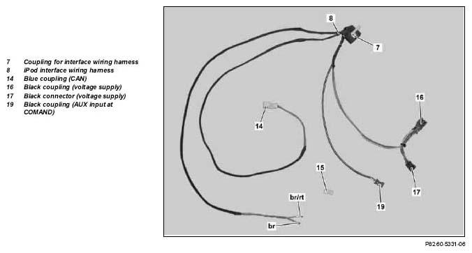
- Open blue connector (15) and remove brown line (br) from blue connector (15).
 The blue connector (15) is still required.
 Courtesy of MERCEDES-BENZ USA
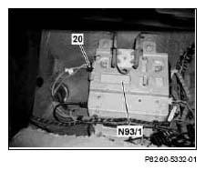
- Disconnect connector (20) from audio gateway control unit (N93/1).
 Risk of breakage!
Do not kink fiber optic cable, route over sharp edges nor bend in radii smaller than 25 mm. Tensile forces on inserts must not exceed 65 N. Do not squeeze fiber optical cable and do not compress with clamps or tie straps.
Risk of breakage!
Do not kink fiber optic cable, route over sharp edges nor bend in radii smaller than 25 mm. Tensile forces on inserts must not exceed 65 N. Do not squeeze fiber optical cable and do not compress with clamps or tie straps.
 Courtesy of MERCEDES-BENZ USA
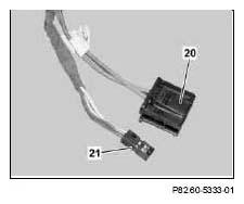
- Remove connector (21) from connector (20).
 Courtesy of MERCEDES-BENZ USA
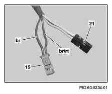
- Remove brown line (br) from contact cavity "4"
of the on-board connector (21) and reinstall in contact cavity "2"
of the blue connector (15) supplied.
- Remove brown/red line (br/r) from contact cavity "2"
of the on-board connector (21) and reinstall in contact cavity "1"
of the blue connector (15) supplied.
 Courtesy of MERCEDES-BENZ USA
- Connect blue connector (15) to blue coupling (14) of iPod interface wiring harness (8).
- Install brown line (br) of iPod interface wiring harness (8) in contact cavity "4"
of the on-board connector (21).
- Install brown/red line (br/rt) of iPod interface wiring harness (8) in contact cavity "2"
of the on-board connector (21).
- Reinstall connector (21) in connector (20).
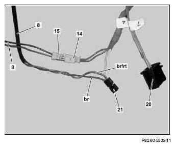 Courtesy of MERCEDES-BENZ USA
- Reconnect connector (20) to audio gateway control unit (N93/1).
Risk of breakage!
Do not kink fiber optic cable, route over sharp edges nor bend in radii smaller than 25 mm. Tensile forces on inserts must not exceed 65 N. Do not squeeze fiber optical cable and do not compress with clamps or tie straps.
- Route the remaining couplings and connectors of the iPod interface wiring harness (8) from the front passenger footwell into the radio recess.
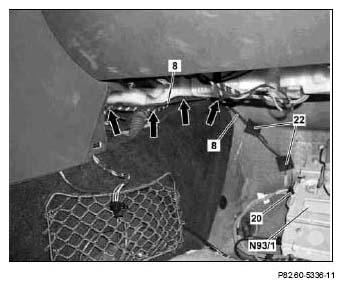 Courtesy of MERCEDES-BENZ USA
- Route the two branch-off lines of the iPod interface wiring harness (8) as per the picture in the footwell and fix into position using two felt strips (22).
The iPod interface wiring harness (8) has to be fastened on the floor with at least two felt strips (22) as illustrated in the picture. Otherwise, there is the risk of damaging the iPod interface wiring harness (8) when the step plate is installed.
- Fasten the two branch-off lines of the iPod interface wiring harness (8) to the on-board wiring harness using cable ties (see arrows).
The remaining couplings and connectors will be connected at a later point in time.
- Fasten the excess length of the iPod interface wiring harness (8) to the on-board wiring harness using cable ties (see arrows).