Redrill glow plug - AR15.20-P-4112-01OG
WARNING: This page does not describe the selected car, but rather 8 other vehicles, including the 2011 Mercedes-Benz ML350, 2010 Mercedes-Benz ML350, 2009 Mercedes-Benz ML320, 2009 Mercedes-Benz GL320, and 2008 Mercedes-Benz ML320. However, it is still accessible from the selected car via links, so may be relevant.
MODIFICATION NOTES
| 9.4.10 |
Value changed: bolt, cylinder head cover on cylinder head |
*BA01.20-P-1001-01P |
CRANKCASE VENTILATION, CYLINDER HEAD COVER
| Number |
Designation |
Engine 642 |
| BA01.20-P-1001-01P |
Bolt, cylinder head cover to cylinder head |
Stage 1, apply |
Nm |
4 |
| Stage 2, initial torque |
Nm |
6 |
| Stage 3, final torque |
Nm |
9 |
PREGLOW SYSTEM
| Number |
Designation |
Engine 642 |
| BA15.20-P-1001-01F |
Glow plug on cylinder head |
M8 |
Nm |
11 |
| M10 |
Nm |
18 |
 Courtesy of MERCEDES-BENZ OF NORTH AMERICA.
 Courtesy of MERCEDES-BENZ OF NORTH AMERICA.
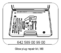
 In order to avoid damage to engine, the chips produced must be suctioned off immediately after every metal-cutting workstep and the bores must be cleaned with the pipe brush from the
  glow plug repair kit. Safety glasses should be worn.
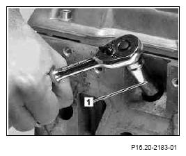
- Place a 4 mm dia. stud extractor (1) on the pin of the glow pin cap and tear off center electrode of the glow plug (R9) clockwise.
 Remove all loose and released parts.
 Courtesy of MERCEDES-BENZ OF NORTH AMERICA.
If the center electrode does not break at the lower end but instead immediately behind the cap of the electrical connection then the center electrode must be torn off again using the 4 mm dia. stud extractor (1). A drilling-out sleeve (2) must be hammered in if this is not possible in order to stabilize the center electrode during drilling-out.
- Hammer drilling-out sleeve (2) using a hammer.
 Courtesy of MERCEDES-BENZ OF NORTH AMERICA.
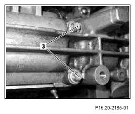
- Remove bolts (3) on the respective cylinder head cover of the broken off glow plug.
 Courtesy of MERCEDES-BENZ OF NORTH AMERICA.
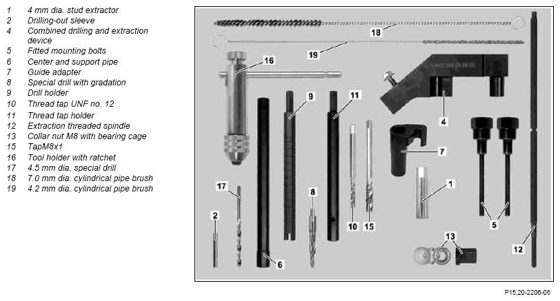
- Place combined drilling and extraction device (4) with the fitted mounting bolts (5) finger-tight on the valve cover.
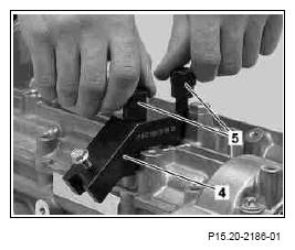 Courtesy of MERCEDES-BENZ OF NORTH AMERICA.
- Push centering and support pipe (6) with the thin diameter from through the guide adapter (7) and attach to the combined drilling and extraction device (4). Place guide adapter (7) at the end stop on the bolt.
- Align combined drilling and extraction device (4) in such a way that the centering and support pipe (6) is easy to move in the row of the glow pin.
- Tighten fitted mounting bolts (5) with a torque
 on cylinder head cover.
- Remove centering and support pipe (6) again and subsequently attach the guide adapter (7) again to the combined drilling and extraction device (4).
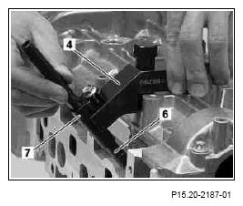 Courtesy of MERCEDES-BENZ OF NORTH AMERICA.
- Use special drill with gradation (8) to drill out the glow pin by 2 to 3 mm.
Only perform steps 11 through 13 if a drilling-out sleeve (2) was hammered in.
- Replace special drill with gradation (8) by the 4.5 mm dia. special drill (17) and drill out the center electrode of the glow pin down to the end stop of the drill holder (9).
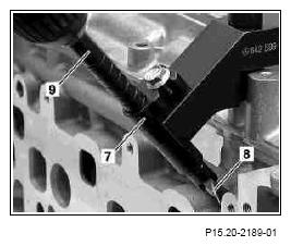 Courtesy of MERCEDES-BENZ OF NORTH AMERICA.
- Replace 4.5 mm dia. special drill (17) with the special drill with gradation (8) again.
Drilling and thread-cutting is required in two stages in order to avoid co-rotation of the glow pin during thread cutting.
- By putting down the special drill with gradation (8) a number of times drill the glow pin up to the marking (A) on the stem of the drill holder (9).
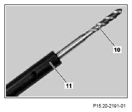
- Clamp thread tap UNF no. 12 (10) into thread tap holder (11) and, led through the combined drilling and extraction device (4), cut a thread in the glow plug as deeply as possible.
Work carefully with thread cutting and lubricate well.
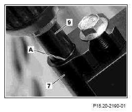 Courtesy of MERCEDES-BENZ OF NORTH AMERICA.
- Bring special drill with gradation (8) again through the combined drilling and extraction device (4) into the slot and drill out the glow plug down to the end stop for the drill holder (9).
- Using thread tap UNF no. 12 (10) again led through the combined drilling and extraction device (4), cut the thread to the maximum possible depth in the glow plug.
Work carefully with thread cutting and lubricate well.
 Courtesy of MERCEDES-BENZ OF NORTH AMERICA.
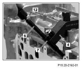
- Lead extraction threaded spindle (12) through the combined drilling and extraction device (4) with a mounted guide adapter (7) and turn in the cut thread of the glow plug hole.
- Push centering and support pipe (6) over the extraction threaded spindle (12) and through the guide adapter (7).
 Courtesy of MERCEDES-BENZ OF NORTH AMERICA.
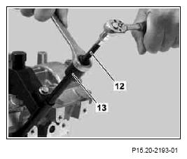
- Turn collar nut M8 with bearing cage (13) on the extraction threaded spindle (12) and pull out the remains of the glow pin. Always counterhold the extraction threaded spindle (12) at the hexagon.
If an increased force is necessary spray the glow pin with antiseize and lightly pound the extraction threaded spindle (12) under tension with a hammer on the hexagon.
 Courtesy of MERCEDES-BENZ OF NORTH AMERICA.
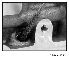
- The now released glow pin bore should first be cleaned to be free of soot and deposits using the 7.0 mm dia. cylindrical pipe brush (18) and then with the 4.2 mm dia. cylindrical pipe brush (19).
 Courtesy of MERCEDES-BENZ OF NORTH AMERICA.
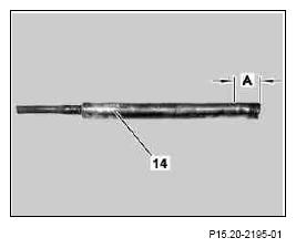
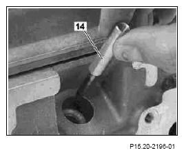
If there is no stop plug available to prevent ingress of chips into the cylinder compartment then the stop plug can be made, as described below, from a drilled out glow plug.
- Shorten removed glow pin residue (14) on the drilled out end by about 15 mm.
- Recut thread in the removed glow pin residue (14) and clean the stem.
- Introduce rest of the glow pin (14) into the clean glow pin shaft as a stop plug.
 Courtesy of MERCEDES-BENZ OF NORTH AMERICA.
 Courtesy of MERCEDES-BENZ OF NORTH AMERICA.
Dimensions:
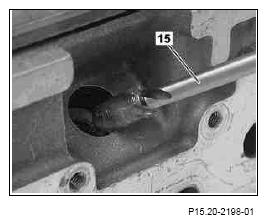
- Wet thread tap M8x1 (15) with grease and recut the thread cleaning in the cylinder head.
- Remove stop plugs using magnets or the extraction threaded spindle.
- Screw glow plug into cylinder head with torque
 Courtesy of MERCEDES-BENZ OF NORTH AMERICA.