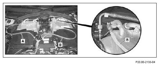
- Connect the connections (A, B) to the service connections of the charge air cooler.
 Courtesy of MERCEDES-BENZ USA
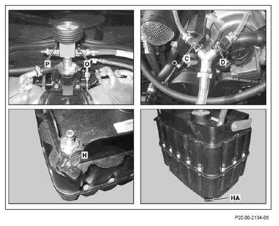
- Close all the valves (C, D, H, HA, O, P) on the control unit, the Y-fitting and the vacuum box.
 Courtesy of MERCEDES-BENZ USA
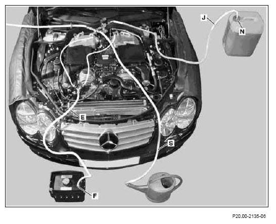
 All the connections described in steps 3 to 5 will be maintained throughout the bleeding process. Interchanging the hoses (E, J, S) will damage the bleeding devices.
- Connect the coolant feed (J) to connection (N).
- Connect the coolant drain (E) to connection (F).
- Lay down the waste air hose (S) in the receptacle.
 Courtesy of MERCEDES-BENZ USA
 Courtesy of MERCEDES-BENZ USA
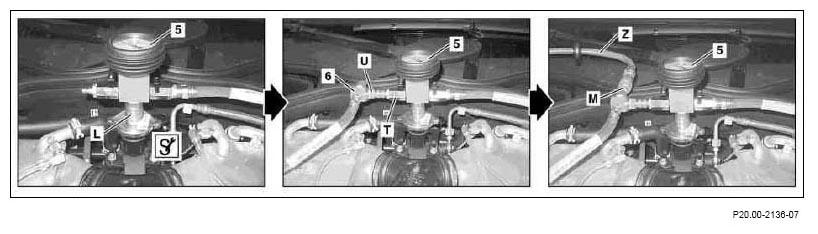
- Connect the control unit (5) to the
 test connection - connection (L) to
the test connection.
test connection - connection (L) to
the test connection.
- Connect the venturi nozzle (6) to the control unit (5) - connection (U) to connection (T).
- Connect the compressed air (Z) to the venturi nozzle (6) - compressed air (Z) to connection (M).
 An audible air discharge is normal.
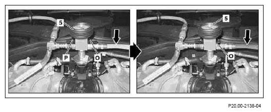
- Generate a vacuum in the control unit (5) - open valve (P).
- By regulating the valve (O) (arrow), draw in the coolant up to the control unit (5) by suction. Then again close valve (O).
 Courtesy of MERCEDES-BENZ USA
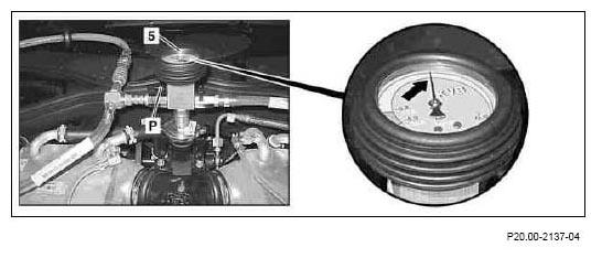
- Test the low temperature circuit for leaks - close valve (P).
The unchanged display (arrow) of the pressure gauge shows that the vacuum has been maintained, thereby indicating the leak tightness of the low temperature circuit.
 Courtesy of MERCEDES-BENZ USA
 Courtesy of MERCEDES-BENZ USA
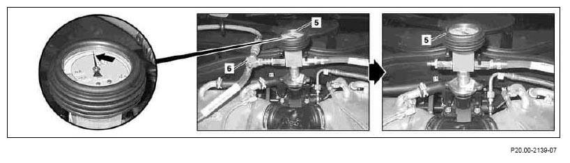
- Detach the venturi nozzle (6) from the control unit (5).
The display of the pressure gauge (arrow) must continue to show a vacuum even after the preparatory tasks have been completed.