Remove/install front axle half - AR33.10-P-0200MB
MODEL 220 with CODE (979) Special protection version with CODE (Z07) Top protection
  |
Remove/Install |
|
|
 |
Risk of death caused
by vehicle slipping or toppling off of the lifting platform. |
Align vehicle between the columns of the hydraulic hoist and position the four support plates below the hoist support points specified by the vehicle manufacturer. |
AS00.00-Z-0010-01A |
 |
Notes on self-locking nuts and bolts |
|
AH00.00-N-0001-01A |
 Installation Installation |
Tighten nuts and bolts of chassis components only in curb condition. |
|
|
| 1 |
Raise vehicle with lifting platform |
|
|
| 2 |
Remove front wheel |
|
|
 |
Remove and install wheels |
|
AP40.10-P-4050Z |
| 3 |
Remove front suspension strut |
|
AR32.25-P-1017MB |
| 4 |
Press track rod joint out of steering knuckle (5). |
|
AR46.40-P-0200-02I |
| |
|
 Thrust piece
 |
Figure |
| |
|
Puller |
Figure |
| |
|
 |
*BA46.40-P-1001-01E |
| 5 |
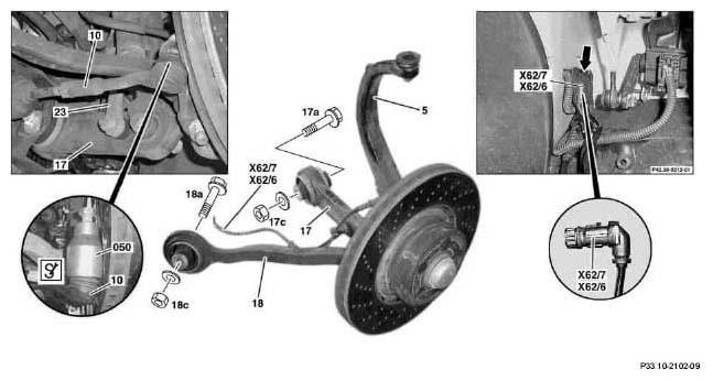
Detach torsion bar link rod (23) from spring link (17). |
|
*BA32.20-P-1001-02H |
| 6 |
Detach brake caliper with brake pads from steering knuckle (5) |
Do not detach brake hose.
To relieve the load on the brake hose, fasten the brake caliper to the vehicle free of tension in order not to damage it during repair work. |
AR42.10-P-0070I |
| 7 |
Separate the connector of the right or left front axle electrical distributor, major assemblies compartment (X62/6 or X62/7) |
|
|
| 8 |
Remove lower engine compartment paneling |
On vehicles with fire extinguisher system, detach pipes in the area of the paneling |
AR61.20-P-1105M |
| 9 |
Remove radius rod (18) from front axle carrier. |
Installation:
Screw on nut (18c) of bolt (18a) until it abuts, but do not tighten yet so that the rubber mount of the torque strut (18) can twist as the suspension deflects. Tighten nut (18c) with the vehicle in curb position. |
|
| |
|
|
*BA33.20-P-1002-01F |
| 10 |
Remove spring link (17) from front-axle carrier. |
Installation:
Screw nut (17c) of bolt (17a) until it abuts, but do not tighten yet, so that the rubber bushing on the spring control arm (17) can turn when the suspension is compressed. Tighten nut (17c) only once the vehicle is ready to drive. |
|
| |
|
|
*BA33.20-P-1001-01F |
| 11 |
Remove front axle half |
|
|
| 12.1 |
Remove upper transverse control arm |
If necessary |
AR33.20-P-0500I |
| 13 |
Install in the reverse order |
|
|
| 14 |
Perform chassis alignment |
|
AR40.20-P-0200MB |
FRONT AXLE TORSION STRUT
| Number |
Designation |
Model 220 except 220.083 / 084/087 / 183/184 / 187 |
| BA32.20-P-1001-02H |
Nut, link rod to spring link |
Nm |
150 |
WHEEL LOCATION, HUB
| Number |
Designation |
Model 220 with Code Z07 |
| BA33.20-P-1001-01F |
Spring link self-locking nut at front axle carrier |
Nm |
210 |
| BA33.20-P-1002-01F |
Self-locking nut, radius rod to front axle carrier |
Nm |
210 |
TRACK ROD
| Number |
Designation |
Model 220 except model 220.083/ 084/087/ 183/184/ 187 |
| BA46.40-P-1001-01E |
Self-locking nut, tie rod to steering knuckle |
1st stage |
Nm |
50 |
| Step 2 |
∠ |
60 |