Check adjustment dimension of drive pinion - AR35.31-P-0550-18A
TEST VALUES FOR REAR AXLE CENTER ASSEMBLY GEAR SET
| Number |
Designation |
Model 129 |
Model 140 |
Model 170 |
| BE35.31-P-1001-03A |
Permissible deviation from specified adjustment dimension on end face of drive pinion |
mm |
-0.02/+0.01 |
-0.02/+0.01 |
-0.02/+0.01 |
TEST VALUES FOR REAR AXLE CENTER ASSEMBLY GEAR SET
| Number |
Designation |
Model 202 |
Model 203 |
Model 208 |
| BE35.31-P-1001-03A |
Permissible deviation from specified adjustment dimension on end face of drive pinion |
mm |
-0.02/+0.01 |
-0.02/+0.01 |
-0.02/+0.01 |
TEST VALUES FOR REAR AXLE CENTER ASSEMBLY GEAR SET
| Number |
Designation |
Model 209 |
Model 210 |
Model 220.063/065/067/083/ 084/087/165/167/183/ 184/187 |
| BE35.31-P-1001-03A |
Permissible deviation from specified adjustment dimension on end face of drive pinion |
mm |
-0.02/+0.02 |
-0.02/+0.01 |
-0.02/+0.01 |
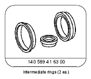
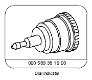
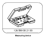
- Mount magnetic disk (052c), part 05 from
 intermediate rings (2 items), on the end face of the drive pinion (47) to measure the basic setting in design terms.
- Insert left measuring device ring (052e), part 01 from
measuring device, from the outside inwards precisely up to the stop in the rear axle housing.
- Insert right measuring device ring (052d), part 02 from
measuring device, from the inside outwards precisely up to the stop in the rear axle housing.
- Insert dial indicator (052a) with measuring pin into the measuring device (052).
- Press adjusting piece (052b), part 10 from
measuring device, against the measuring device (052) and position dial indicator (052a) on "0" under 2 mm preload. Tighten clamp screw, checking the "0" position of the dial indicator (052a) and re-align if necessary.
 The measuring pin for the dial indicator (052a) is screwed into the adjusting piece (052b)
 When inserting the measuring device (052) into the rear axle housing ensure that the measuring pin of the dial indicator (052a) not damaged in the bore.
- Insert the measuring device (052) from the left bore into the rear axle housing.
- Read off adjustment dimension (A).
The adjustment dimension (A) must be within the tolerance.
- Take the measuring device (052) and magnetic disk (052c) out of the rear axle housing.
The adjustment dimension (A) is the design basic setting of the drive pinion, the deviation in basic setting (a) having to be within the permissible tolerance in the positive or negative direction. The deviation in basic setting (a) is the dimension which is to be read off on the end face of the drive pinion.
If the adjustment dimension is outside the tolerance, the installed shim should be reground or a new shim of the appropriate thickness should be installed and a new spacer sleeve should be used for the tapered roller bearings in order to guaranteed satisfactory operation.