Removing and installing front axle half - AR33.10-P-0200B
MODEL 170, 202, 208
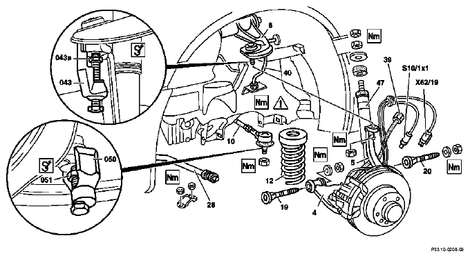
  |
Removal, installation |
|
|
| 1 |
Remove front wheel |
|
AP40.10-P-4050Z |
| 2 |
Remove front spring (12) |
|
AR32.20-P-0200B |
| 3.1 |
Disconnect VSS sensor connectors (X62/19) and left front brake pad wear sensor connector (S10/1x1) in component compartment. |
 Model 202
Remove front axle cable set through the wheel house |
|
| 3.2 |
Disconnect speed sensor connectors and brake pad wear sensor on wheel house |
Models 170, 208 |
|
 |
Risk of poisoning
due to consuming brake fluid. Risk of injury
due to brake fluid contacting the skin or eyes. |
Only pour brake fluid into suitable, appropriately marked containers. Wear protective clothing and safety glasses when handling brake fluid. |
AS42.50-Z-0001-01A |
| 4 |
Unscrewing brake hose (39) from brake pipe (40) |
Protect pipes against contamination |
|
| |
|
 Installation Installation  The brake hose must not be twisted after tightening
 |
*BA42.10-P-1001-04A |
| |
|
 |
*WH58.30-Z-1003-11A |
|
Notes on installing brake hoses |
Models 129, 140, 170, 202, 208, 210 |
AH42.10-P-9406-01A |
|
Notes on brake fluid |
All models |
AH42.50-P-0001-01A |
| 5 |
Remove torsion bar (28) from lower wishbone |
|
*BA32.20-P-1001-02C |
| 6 |
Remove tie rod (10) from steering knuckle |
Check rubber boot and ball joint for damage and wear |
*BA46.40-P-1002-01A |
| |
|
 Puller (050)
 |
Fig 2 |
| |
|
Thrust piece (051) |
Fig 3 |
| 7 |
Unscrew shock absorber (47) at upper fixing |
|
*BA32.25-P-1002-01B |
| |
|
|
*BA32.25-P-1001-01B |
| 8 |
Support lower wishbone (4) and remove from frame floor |
Model 170
First remove the lower engine compartment lining |
AR33.10-P-0200-01B |
| |
|
Observe technical modification ↓ |
*BA33.20-P-1009-01A |
 |
|
Lower wishbone bearing bracket |
BT33.20-P-9308-01B |
| 9 |
Remove steering knuckle (5) from upper wishbone (6) |
Check rubber boot and ball joint for damage and wear |
*BA33.20-P-1002-01A |
| |
|
Puller (043) |
Fig 4 |
| |
|
Thrust piece (043a) |
Fig 5 |
| 10 |
Remove front axle half |
|
|
| 11 |
Remove upper wishbone |
|
AR33.20-P-0500B |
| 12 |
Install in reverse order |
|
|
| Installation |
Replace self-locking bolts and nuts |
Tighten fixing nuts in ready-to-drive condition |
|
| 13 |
Bleed front brake system |
|
AR42.10-P-0010A |
| 14 |
Perform chassis alignment check |
|
AR40.20-P-0200A |
FRONT AXLE TORSION BAR
| Number |
Designation |
Model 202 |
Model 208 |
| BA32.20-P-1001-02C |
Self-locking nut for fixing bracket on wishbone |
Nm |
20 |
20 |
FRONT AXLE TORSION BAR
| Number |
Designation |
Model 170 |
| BA32.20-P-1001-02C |
Self-locking nut for fixing bracket on wishbone |
Nm |
20 |
FRONT AXLE SHOCK ABSORBER
| Number |
Designation |
Model 202 |
Model 208 |
Model 170 |
| BA32.25-P-1001-01B |
Nut, shock absorber on front end |
Nm |
18 |
18 |
18 |
| BA32.25-P-1002-01B |
Lock nut, shock absorber on front end |
Nm |
30 |
30 |
30 |
WHEEL LOCATION, WHEEL HUB
| Number |
Designation |
Model 170 |
Model 202 |
Model 208 |
| BA33.20-P-1002-01A |
Self-locking nut, follower joint of upper wishbone to steering knuckle |
First time |
Nm |
45 |
45 |
45 |
| Check torque |
Nm |
- |
- |
- |
| BA33.20-P-1009-01A |
Self-locking nut, lower wishbone to frame |
|
Nm |
120 |
120 |
120 |
BRAKE PIPES, BRAKE HOSES
| Number |
Designation |
Model 202 |
Model 170 |
Model 208 |
| BA42.10-P-1001-04A |
Brake pipe to brake hose |
Nm |
14 |
14 |
14 |
TIE ROD
| Number |
Designation |
Model 170 |
Model 202 |
Model 208 |
| BA46.40-P-1002-01A |
Self-locking nut of tie rod to steering knuckle |
yellow |
Nm |
50 |
50 |
50 |
| silver or blue |
Nm |
- |
- |
- |
COMMERCIALLY AVAILABLE TOOLS
| Number |
Designation |
| WH58.30-Z-1003-11A |
Open double end box wrench a/f 8x9 mm or a/f 10x11 mm |