Removing and installing brake booster - AR43.10-P-0350A
WARNING: This page does not describe the selected car, but rather 42 other vehicles, including the 1999 Mercedes-Benz S600, 1999 Mercedes-Benz S500, 1999 Mercedes-Benz S420, 1999 Mercedes-Benz S320, and 1999 Mercedes-Benz CL600. However, it is still accessible from the selected car via links, so may be relevant.
MODEL 129, 140, 170, 202, 210
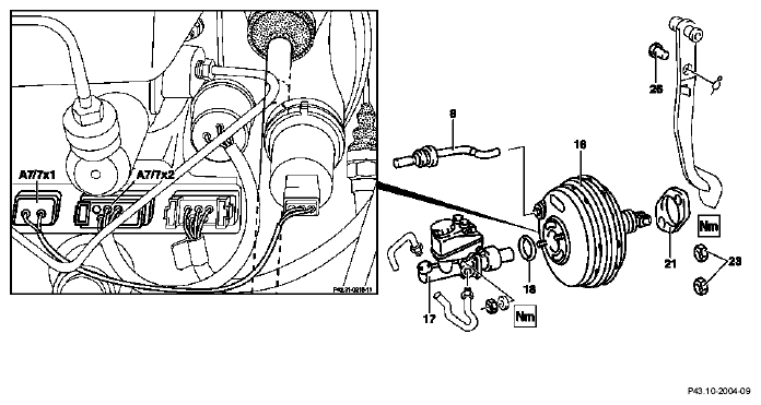 Courtesy of MERCEDES-BENZ OF NORTH AMERICA.
  |
Removing, installing |
|
|
 |
Risk of poisoning
from swallowing brake fluid. Risk of injury
from skin and eye contact with brake fluid |
Pour brake fluid only into suitable and appropriately marked containers. Wear protective clothing and eye protection when handling brake fluid. |
AS42.50-Z-0001-01A |
 |
Notes on brake fluid |
|
AH42.50-P-0001-01A |
|
Notes on repairs to brake system |
|
AH42.00-P-0003-01A |
| 1 |
Remove, install stepped tandem brake master cylinder |
Installation:
Replace O-ring (18). |
AR42.10-P-0310A |
| 2 |
Remove, install ASR charging pump |
Models 129, 140 up to 31.5.94 with ASR code 471a |
AR42.45-P-0818A |
 |
Checking |
|
|
| 3 |
Check master brake cylinder for leaks at rear piston |
Visual inspection: |
|
|
Notes if loss of brake fluid is not visible externally |
|
AH42.10-P-9406-02A |
| 4 |
Unscrew or unplug vacuum line (8) from brake booster (16) |
 Operate brake pedal several times until the vacuum in the brake booster is reduced (only for plug-in vacuum lines).
 |
|
| |
|
 |
*BA43.10-P-1001-01A |
| 5 |
Unplug connector (A7/7x1, A7/7x2) from BAS control module or, on vehicles with ESP, unplug connectors from BAS solenoid valve release switch and BAS diaphragm travel sensor on brake booster |
On vehicles with BAS and ESP, the BAS control module is integrated into the ESP control module. |
|
| 6 |
Remove cover below instrument panel |
Model 129 |
ra68001290150x |
| |
|
Model 140 |
ra68001400150x |
| |
|
Model 170 |
|
| |
|
Model 202 |
AR68.10-P-1500E |
| |
|
Model 210 |
AR68.10-P-1500F |
| 7 |
Unhook brake pedal return spring (25) |
Installation:
↓ |
|
| |
|
Remove and adjust stop lamp switch |
AR42.10-P-0040A |
| 8 |
Pull off retainer and pull out pin (26) |
|
|
| 9 |
Unscrew nuts (23) from carrier (22) |
|
*BA43.10-P-1002-01A |
| 10 |
Remove brake booster (16) |
Do not damage the brake booster control housing. |
|
|
Checking |
|
|
| 11 |
Check gasket (21) |
Check gasket (21) for damage and proper seating, and replace if necessary. |
|
| 12 |
Install in the reverse order |
|
|
| 13 |
Adjust and check parking shift lock |
Transmission 722.3/5 |
ra2703722d740x |
| |
|
Transmission 722.6 (NAG transmission) |
AR27.60-P-0965A |
PNEUMATIC BRAKE BOOSTER
| Number |
Designation |
Model 129 up to 09/89 |
Model 129 as of 10/89 |
Model 140 |
Model 202 |
| BA43.10-P-1001-01A |
Vacuum line to brake booster |
Nm |
30 |
30 |
30 |
30 |
| BA43.10-P-1002-01A |
Nut, brake booster carrier to front end |
Nm |
15 |
20 |
20 |
20 |
PNEUMATIC BRAKE BOOSTER
| Number |
Designation |
Model 210 |
Model 170 |
| BA43.10-P-1001-01A |
Vacuum line to brake booster |
Nm |
30 |
- |
| BA43.10-P-1002-01A |
Nut, brake booster carrier to front end |
Nm |
20 |
20 |