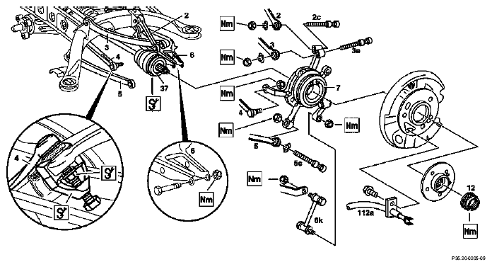
Remove/install wheel carrier - AR35.20-P-0115A
WARNING: This page does not describe the selected car, but rather 42 other vehicles, including the 1999 Mercedes-Benz S600, 1999 Mercedes-Benz S500, 1999 Mercedes-Benz S420, 1999 Mercedes-Benz S320, and 1999 Mercedes-Benz CL600. However, it is still accessible from the selected car via links, so may be relevant.
MODEL 140
 Courtesy of MERCEDES-BENZ OF NORTH AMERICA.
 MODIFICATION NOTES
| 3.5.07 |
Self-locking nut, tie rod to wheel carrier, silver or blue M10x1, 5 |
New tightening torque applied, see Fig. item 4 |
*BA35.20-P-1002-04A |
| 25.5.07 |
Self-locking nut, strut rod to wheel carrier, M16 |
|
*BA35.20-P-1002-03A |
| Figure item, etc. |
Work instructions |
|
|
 |
Risk of death
caused by vehicle slipping or toppling off of the lifting platform. |
Align vehicle between columns of vehicle lift and position four support plates at vehicle lift support points specified by vehicle manufacturer. |
AS00.00-Z-0010-01A |
 |
Notes on self-locking nuts and bolts |
|
AH00.00-N-0001-01A |
|
While working on the rear axle care must be taken to ensure that the surface of all aluminum components do not get any scratches, cracks and notches. Otherwise the service life of the parts will be affected |
|
|
 |
Only tighten nuts and bolts of chassis components when vehicle is in a ready-to-drive condition. |
|
|
|
Remove/install brake shoes of parking brake |
|
AR42.20-P-0530A |
|
Remove/install rpm sensor at wheel carrier |
Vehicles as of 07/94 |
|
| Installation |
Install camber strut, tension arm, torque strut, track rod and spring control arm at wheel carrier |
The rear-axle shaft must be horizontal when tightening the nuts. |
|
 Installation Installation |
Check and adjust toe on rear axle |
If necessary |
AR40.20-P-0332A |
| 2 |
Camber strut |
 |
*BA35.20-P-1002-02A |
| 2c, 3e, 5c |
Fit bolts |
Installation:
Replace fitted bolts. |
|
| 3 |
Torque strut |
|
*BA35.20-P-1002-03A |
| 4 |
Tie rod |
 |
Figure |
| |
|
Press ball head bolt firmly into the cone, if necessary counterhold with Allen wrench.
Installation:
Clean grease off the ball head bolt as well as beveled seat in the wheel carrier. |
Figure |
| |
|
|
*BA35.20-P-1002-04A |
 |
Surface protection of track rod at wheel carrier modified |
Vehicles as of 01/97 |
BT35.20-P-0004-01A |
|
Bolted connection, track rod to wheel carrier modified |
Vehicles as of 23/6/98 |
BT35.20-P-0009-01A |
| 5 |
Thrust arm |
|
*BA35.20-P-1002-05A |
| 6 |
Spring control arm |
|
*BA35.20-P-1002-01A |
| 6k |
Stabilizer bar link rod |
|
*BA32.20-P-1001-04B |
| |
|
|
*BA32.20-P-1002-04B |
| 7 |
Wheel carrier |
Remove rear axle shaft from wheel carrier. |
|
| 12 |
Twelve-point collar nut |
Detach/attach twelve-point collar nut of rear axle shaft and secure. |
AR35.30-P-0115-01A |
| |
|
|
*BA35.30-P-1001-01A |
| 37 |
Rear axle shaft |
Pull rear axle shaft out of rear axle shaft flange.
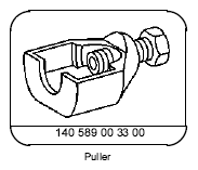
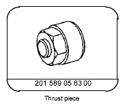
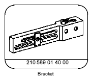
If the rear axle shaft is difficult to remove: ↓ |
|
| |
|
Vehicle up to 31.01.96 |
AR35.30-P-0115-03A |
| |
|
|
Fig 5 |
| |
|
Vehicles as of 01.02.96 |
AR35.30-P-0115-03B |
| |
|
|
Fig 5 |
| |
|
|
Fig 4 |
|
Rear axle shafts with forged centers (without core hole) |
As of 02/96 |
BT35.30-P-0005-01A |
| 112 A |
Brake cable |
Remove/install rear brake cable. |
AR42.20-P-0525A |
REAR AXLE STABILIZER BAR
| Number |
Designation |
Model 140 |
Model 140 with level control or ADS |
| BA32.20-P-1001-04B |
Self-locking nut for attaching torsion bar link rod at torsion bar |
Nm |
40 |
40 |
| BA32.20-P-1002-04B |
Self-locking nut for attaching torsion bar link rod to wheel hub |
Nm |
40 |
40 |
SPRING CONTROL ARM
| Number |
Designation |
Model 140 |
| BA35.20-P-1002-01A |
Self-locking nut, spring control arm to wheel carrier. |
Stage 1 |
Nm |
120 |
| Stage 2 |
∠° |
- |
CAMBER STRUT
| Number |
Designation |
Model 140 |
| BA35.20-P-1002-02A |
Self-locking nut, camber strut to wheel carrier. |
M10 |
Nm |
- |
| M12 |
Nm |
70 |
TIE ROD
| Number |
Designation |
Model 140 |
| BA35.20-P-1002-04A |
Self-locking nut, tie rod at wheel carrier |
yellow M10 X 1 |
Nm |
30 |
| silver or blue M10 X 1 |
Nm |
25 |
| silver or blue M10 X 1.5 |
Stage 1 |
Nm |
20 |
| Stage 2 |
∠ ° |
45 |
TORQUE STRUT
| Number |
Designation |
Model 140 |
| BA35.20-P-1002-03A |
Self-locking nut, torque strut to wheel carrier |
M12 |
Nm |
70 |
| M16 |
Nm |
230 |
TORQUE STRUT
| Number |
Designation |
Model 140 |
| BA35.20-P-1002-05A |
Self-locking nut, thrust arm to wheel carrier |
M10 |
Nm |
- |
| M12 |
Nm |
70 |
| |
∠ ° |
- |
REAR AXLE SHAFT
| Number |
Designation |
Model 140 |
| BA35.30-P-1001-01A |
Collar nut, rear axle shaft to rear axle shaft flange |
Stage 1 |
Nm |
320 |
| Stage 2 |
∠ ° |
- |
 Courtesy of MERCEDES-BENZ OF NORTH AMERICA.
 Courtesy of MERCEDES-BENZ OF NORTH AMERICA.
 Courtesy of MERCEDES-BENZ OF NORTH AMERICA.
 Courtesy of MERCEDES-BENZ OF NORTH AMERICA.