| 1 |
- Retrieve the DTC of instrument cluster using M-MDS. (See DTC INSPECTION
.)
- Is the DTC detected?
|
Yes |
Go to applicable DTC troubleshooting procedure.
(See DTC TABLE
.) |
| No |
Go to the next step. |
| 2 |
- Cool down the engine.
- Switch the ignition ON.
- Verify that the high engine coolant temperature warning light (red) condition.
- Does the high engine coolant temperature warning light (red) illuminate or flash while 3-30 s after the engine switch is turned to ON position?
|
Yes |
Go to the next step. |
| No |
Go to Step 5. |
| 3 |
- Start the engine.
- Monitor PCM PID ECT using the M-MDS.
- Verify that the low engine coolant temperature indicator light (blue) condition when the ECT monitoring value above 55°C {131°F}
- Does the low engine coolant temperature indicator light (blue) illuminate?
|
Yes |
Go to Step 5. |
| No |
Go to the next step. |
| 4 |
- Monitor the PCM PID ECT using the M-MDS.
- Is the PID ECT monitoring value for following value?
- Above 120°C {248°F} when high engine coolant temperature warning light (red) flashes.
- Above 125°C {257°F} when high engine coolant temperature warning light (red) illuminates.
|
Yes |
Troubleshooting is completed. (The system is normal.) |
| No |
Go to the next step. |
| 5 |
- Do the speedometer and tachometer indicate correct?
|
Yes |
Go to the next step. |
| No |
Go to Step 7. |
| 6 |
- Turn on and off both low engine coolant temperature indicator light (blue)/high engine coolant temperature warning light (red) using M-MDS instrument cluster active command modes. (See ACTIVE COMMAND MODES TABLE
.)
- Do the both low engine coolant temperature indicator light (blue)/high engine coolant temperature warning light (red) turn on and off according to active command modes?
|
Yes |
Inspect the ECT sensor.
(See ENGINE COOLANT TEMPERATURE (ECT) SENSOR INSPECTION
.) |
| No |
Replace the instrument cluster.
(See INSTRUMENT CLUSTER REMOVAL/INSTALLATION
.) |
| 7 |
- Disconnect the negative battery cable.
- Measure the resistance between the DLC-2 terminals F and E.
- Is the resistance below 60 ohms?
|
Yes |
Go to the next step. |
| No |
Go to Step 9. |
| 8 |
- Disconnect the negative battery cable.
- Inspect the DLC-2 terminals F and E for short to power supply or ground.
- Is there any malfunction?
|
Yes |
Inspect the wiring harness and CAN system-related module.
Repair or replace the malfunctioning part. |
| No |
Replace the instrument cluster. |
| 9 |
- Switch the ignition OFF (LOCK).
- Inspect the instrument cluster connector terminals for poor connection (such as damaged/pulled-out pins, and corrosion).
- Are the terminals normal?
|
Yes |
Go to the next step. |
| No |
Repair or replace the terminal. |
| 10 |
- Disconnect the negative battery cable.
- Measure the resistance between the instrument cluster connector terminals 2B and 2D.
- Is the resistance 114-126 ohms?
|
Yes |
Inspect the wiring harness and CAN system-related module.
Repair or replace the malfunctioning part. |
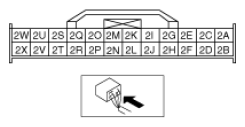 Courtesy of MAZDA MOTORS CORP. Courtesy of MAZDA MOTORS CORP.
|
No |
Replace the instrument cluster. |