| 1 |
VERIFY FREEZE FRAME DATA HAS BEEN RECORDED
- Has FREEZE FRAME DATA been recorded?
|
Yes |
Go to the next step. |
| No |
Record FREEZE FRAME DATA on the repair order, then go to the next step. |
| 2 |
VERIFY RELATED REPAIR INFORMATION AVAILABILITY
- Verify related Service Bulletins and/or on-line repair information availability.
- Is any related Service Bulletins available?
|
Yes |
Perform repair or diagnosis according to the available Service Bulletins.
- If the vehicle is not repaired, go to the next step.
|
| No |
Perform the PCM reprogramming procedure.
Then go to the next step. |
| 3 |
VERIFY RELATED PENDING CODE OR STORED DTCS
NOTE:
- Do not clear the DTCs or reset the PCM.
- Access the PCM and record the ECT PID from the freeze frame data.
- The freeze frame data is used to recreate the concern.
- Switch the ignition to off, then to ON (engine off).
- Verify the related PENDING CODE or stored DTCs using the M-MDS.
- Are any DTCs present other than the following:
- P0171:00, P0174:00, P2195:00, P2197:00, P219A:00 or P219B:00?
|
Yes |
Go to the appropriate DTC troubleshooting procedures.
(See DTC TABLE
.) |
| No |
Go to the next step. |
| 4 |
PERFORM VISUAL INSPECTION ON INTAKE AIR SYSTEM AND ALL VACUUM HOSES
- Switch the ignition to off.
- Inspect the entire air intake system from the MAF sensor to the intake manifold for leaks such as:
- Hoses connecting to the MAF sensor assembly
- Cracked or punctured intake air tube
- Loose connections on the intake air tube at the air cleaner housing or throttle body
- Hoses connecting to the throttle body
- Throttle body assembly or gasket
- Inspect the entire length of all the vacuum hoses for:
- Correct connections
- Damage or cracks
- Damaged or cracked vacuum tees
- Inspect the intake manifold or gasket for leaks.
- Verify the integrity of the PCV system.
- Verify the proper PCV valve part number.
- Inspect the exhaust system for leaks at flanges and gaskets.
- Inspect for an incorrectly seated engine oil dipstick, dipstick tube, or oil fill cap.
- Is a concern present?
|
Yes |
Go to the next step. |
| No |
Go to Step 7. |
| 5 |
LOCATE VACUUM LEAK
CAUTION:
- Do not clamp or pinch a hard plastic hose. Use a vacuum cap or equivalent to restrict the hose.
NOTE:
- Restricting the EVAP vapor hose while the EVAP emission canister is purging may shift the SHRTFT. Perform a visual inspection if necessary.
- When monitoring for a decrease in the SHRTFT PIDs in the following steps, if SHRTFT1 equals +15 % and the hose is restricted, SHRTFT1 decreases to -7 %. The total decrease in the SHRTFT PIDs equals 22 %.
- Locate the vacuum hose joint for the intake air and PCV systems.
- For P219A:00:
- Access the PCM and monitor the SHRTFT1 PID.
- For P219B:00:
- Access the PCM and monitor the SHRTFT2 PID.
- Restrict the vacuum lines one at a time for 30 s. If a vacuum leak in the intake is present, the SHRTFT PID values decrease as the hose is restricted.
- Is the decrease in the SHRTFT PIDs more than 15 % when one of the vacuum hoses is restricted?
|
Yes |
Go to the next step. |
| No |
Inspect the intake air system for a vacuum leak in the intake manifold or intake gaskets. Repair if necessary.
Go to the next step. |
| 6 |
VACUUM LEAK REPAIR VERIFICATION
NOTE:
- If the freeze frame ECT PID is available, stabilize the engine at the temperature recorded by the freeze frame data.
- If the freeze frame ECT PID is available, stabilize the engine at the temperature recorded by the freeze frame ECT PID. If the freeze frame ECT PID is not available, maintain the engine coolant temperature between 82-101 °C {180-215 °F} and the intake air temperature at less than 46 °C {115 °F}.
- For P219A:00:
- Access the PCM and monitor the SHRTFT1 (PER) PID.
- For P219B:00:
- Access the PCM and monitor the SHRTFT2 (PER) PID.
- Allow the engine to stabilize at the temperature necessary to recreate the concern.
- Record the SHRTFT1 and SHRTFT2 PID values.
- Switch the ignition to off.
- Repair the vacuum leak.
- Start the engine and run it at idle.
- Allow the engine to stabilize at the temperature necessary to recreate the concern.
- Compare the recorded SHRTFT PID values, prior to the vacuum leak repair, to the current SHRTFT PID values.
- Is the decrease in the SHRTFT PIDs greater than 15 %?
|
Yes |
Troubleshooting is completed.
Go to Step 22. |
| No |
A vacuum leak is still present.
Reinspect step 5. |
| 7 |
CHECK FUEL PRESSURE
WARNING:
- Fuel line spills and leakage are dangerous. Fuel can ignite and cause serious injuries or death. Fuel can also irritate skin and eyes. To prevent this, always complete the "BEFORE REPAIR PROCEDURE".
NOTE:
- For vehicle specific fuel pressure ranges, refer to the FUEL LINE PRESSURE INSPECTION
.
- Remove the jumper wire(s).
- Connect the A/F sensor connector.
- Relieve the fuel pressure.
- Connect the mechanical fuel pressure gauge.
- Pressurize the fuel system.
- Switch the ignition to ON (engine running).
- Allow the fuel pressure to stabilize.
- Switch the ignition to off.
- Switch the ignition to ON (engine running).
- Measure the fuel pressure.
- Is the fuel pressure within the range for the vehicle being diagnosed?
|
Yes |
Go to the next step. |
| No |
Go to Step 11. |
| 8 |
VERIFY FUEL SYSTEM FOR PRESSURE STABILITY-FAST LEAKDOWN
- Mechanical fuel pressure gauge connected.
- Switch the ignition to ON (engine running).
- Allow the fuel pressure to stabilize
- Record the stabilized reading
- Switch the ignition to off.
- Monitor the fuel pressure for 10 s.
- Measure the fuel line pressure after 10 s.
- Does the fuel pressure remain within 34 kPa {0.35 kgf/cm2
, 4.9 psi} of the recorded reading after 10 s?
|
Yes |
Go to Step 10. |
| No |
Go to the next step. |
| 9 |
INSPECT FOR EXTERNAL FUEL LEAK
- Inspect the fuel tank, lines, and filler pipe for a fuel leak.
- Is a concern present?
|
Yes |
Repair for fuel leakage, then go to Step 22. |
| No |
Go to the next step. |
| 10 |
VERIFY FUEL SYSTEM FOR PRESSURE STABILITY-SLOW LEAKDOWN
- Continue to monitor the fuel pressure for 1 min.
- Does the fuel pressure remain within 34 kPa {0.35 kgf/cm2
, 4.9 psi} of the recorded reading after 1 min?
|
Yes |
Perform the "INTERMITTENT CONCERN TROUBLESHOOTING" procedure.
(See INTERMITTENT CONCERN TROUBLESHOOTING
.) |
| No |
Go to Step 19. |
| 11 |
INSPECT SYSTEM INTEGRITY
- Visually inspect the complete fuel delivery system for damage and leakage.
- Check the following:
- Fuel lines and connections
- Relays
- Fuel tank
- Fuel pump
- Fuel pressure regulator
- Fuel pulse damper
- Fuel rail at fuel injectors
- Damaged connector pins
- Electrical connectors not fully engaged
- Verify that the vehicle has followed the maintenance schedule (For Mexico specs.).
- Verify that the fuse integrity.
- Verify that the battery is fully charged.
- Verify that there is clean sufficient fuel.
- Is a concern present?
|
Yes |
Repair if necessary.
Go to Step 22. |
| No |
Go to the next step. |
| 12 |
INSPECT FUEL LINE PRESSURE
|
Yes |
Go to Step 15. |
| No |
Go to the next step. |
| 13 |
INSPECT FUEL PUMP GROUND CIRCUIT FOR OPEN CIRCUIT IN WIRING HARNESS
NOTE:
- Refer to the
Wiring Diagrams Manual for schematic and connector information.
- Switch the ignition to off.
- Disconnect the FP and fuel pump relay connectors.
- Verify that continuity between FP terminal D (wiring harness-side) and ground.
- Is there any continuity?
|
Yes |
Go to the next step. |
| No |
Repair for open circuit, then go to Step 22. |
| 14 |
INSPECT FUEL PUMP POWER CIRCUIT FOR OPEN CIRCUIT IN WIRING HARNESS
NOTE:
- Refer to the
Wiring Diagrams Manual for schematic and connector information.
- Fuel pump relay is removed.
- FP connector is disconnected.
- Verify that continuity between FP terminal B (wiring harness-side) and fuel pump relay (wiring harness-side) terminal C (wiring harness-side).
- Is there any continuity?
|
Yes |
Go to Step 18. |
| No |
Repair for open circuit, then go to Step 22. |
| 15 |
CHECK SEPARATION LEVEL OF ETHANOL/WATER MIXTURE AND GASOLINE IN FUEL
NOTE:
- This step requires the use of a locally obtained 200 ml beaker and a 25 ml graduated cylinder.
- After approximately 3 minutes of standing, the ethanol and water mixes together and settles to the bottom of the 25 ml graduated cylinder. The gasoline rises to the top.
- Fill the 200 ml beaker with 5 ml of clean water.
- Use the pressure relief valve on the mechanical fuel gauge to drain 22 ml of fuel into an approved clean container.
- Pour 20 ml of fuel from the approved clean container into the 25 ml graduated cylinder.
- Add enough water from the 200 ml beaker to the 25 ml graduated cylinder to bring the total volume of liquid to 24 ml.
- Insert a stopper plug in the opening of the 25 ml graduated cylinder.
- Firmly hold the stopper in place and shake the 25 ml graduated cylinder to mix the water and fuel.
- Allow the liquid to stand and separate for approximately 3 minutes.
- Record the separation level from the 25 ml graduated cylinder where the ethanol/water mixture and gasoline meet.
- Did the ethanol/water mixture and gasoline separate?
|
Yes |
Go to the next step. |
| No |
Complete all steps before continuing.
The ethanol/water mixture will separate from the gasoline. If the fuel does not appear to separate, then the fuel is either 100 % ethanol or a mixture of ethanol and water. |
| 16 |
CALCULATE PERCENTAGE OF ETHANOL IN FUEL
NOTE:
- Use the illustration as an example for calculating the percentage of ethanol using the following steps. If the separation level is at 14 ml {14 cc, 0.85 in3
} the calculation is: 14 min 4, then multiply by 5 to equal 50. The percentage of ethanol in the fuel is 50 %.
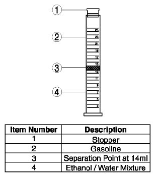 Courtesy of MAZDA MOTORS CORP. Courtesy of MAZDA MOTORS CORP.
- Switch the ignition to off.
- Take the recorded separation level from the previous step and subtract the amount of water added.
- Multiply the new value by 5. This new value is the percentage of ethanol in the fuel
- Record the calculated percentage of ethanol in the fuel.
- Is any ethanol present in the fuel?
|
Yes |
Go to the next step. |
| No |
Go to Step 18. |
| 17 |
DETERMINE IF PERCENTAGE OF ETHANOL IN FUEL IS LESS THAN 10 %
- Verify the recorded (calculated) percentage of ethanol in the fuel.
- Is the calculated percentage of ethanol in the fuel less than 10 %?
|
Yes |
Go to the next step. |
| No |
Replace the fuel.
Advice the customer of the correct fuel type required for this vehicle. Refer to the
Owner's Manual Literature for additional information.
Go to Step 22. |
| 18 |
INSPECT FUEL PRESSURE LEAKDOWN
|
Yes |
Go to Step 20. |
| No |
Go to the next step. |
| 19 |
INSPECT FUEL INJECTOR FLOW AND LEAKAGE
NOTE:
- Observe the Warnings, Cautions, and Notes.
- Inspect the fuel injectors for leakage and flow rate using the injector flow tester or other method such as inspecting the intake manifold for fuel.
- Are the test results satisfactory?
|
Yes |
Go to the next step. |
| No |
Replace the suspect fuel injector, then go to Step 22. |
| 20 |
MONITOR FUEL PRESSURE WHILE ROAD TESTING VEHICLE
WARNING:
- Strict observance of posted speed limits and attention to driving conditions are mandatory when performing the road test. Failure to follow these instructions may result in personal injury.
NOTE:
- Some concerns may only be present during certain fuel level conditions. Determine the fuel level at the time of the concern. Access the information from the customer information worksheet and the customer.
- Switch the ignition to off.
- Securely route the mechanical gauge so that the gauge is viewable while road testing the vehicle.
- Start the engine and run it at idle.
- Warm up the engine to normal operating temperature.
- Monitor the mechanical gauge.
- From a stop, accelerate to 89 km/h (55 mph) at full throttle.
- Repeat 3 times.
- Is the fuel pressure always greater than 240 kPa {2.45 kgf/cm2
, 34.8 psi}?
|
Yes |
Unable to duplicate or identify the concern at this time.
Go to the next step. |
| No |
Go to the next step. |
| 21 |
INSPECT FUEL SUPPLY LINE FOR RESTRICTION
NOTE:
- Observe the Warnings, Cautions, and Notes.
- Switch the ignition to off.
- Disconnect the fuel supply line at the fuel rail.
- Disconnect the fuel supply line at the fuel pump.
- Verify the fuel supply line for restriction.
- Apply 21-34 kPa {0.22-0.34 kgf/cm2
, 3.1-4.9 psi} air pressure to the fuel supply line.
- Does air flow freely through the line?
|
Yes |
Replace the fuel filter (low-pressure side).
Go to the next step. |
| No |
Repair the cause of the restriction, then go to the next step. |
| 22 |
VERIFY TROUBLESHOOTING OF DTC P219A:00, P219B:00 HAS BEEN COMPLETED
|
Yes |
Repeat the inspection from Step 1.
Go to the next step. |
| No |
Go to the next step. |
| 23 |
VERIFY AFTER REPAIR PROCEDURE
|
Yes |
Go to the applicable DTC inspection.
(See DTC TABLE
.) |
| No |
Troubleshooting completed. |