Fuel Gauge Sender: Service and Repair
FUEL GAUGE SENDER UNIT REMOVAL/INSTALLATIONFuel Gauge Sender Unit
1. Remove the fuel gauge sender unit.
2. Install in the reverse order of removal.
Fuel Gauge Sender Sub-Unit
WARNING:
- Fuel line spills and leakage are dangerous. Fuel can ignite and cause serious injuries or death and damage. Fuel can also irritate skin and eyes. To prevent this, always complete the "Fuel Line Safety Procedure".
- Fuel line spills and leakage are dangerous. Fuel can ignite and cause serious injuries or death and damage. Fuel can also irritate skin and eyes. To prevent this, before performing the fuel gauge sender sub-unit removal/installation, always complete the "Fuel Leak Inspection After Fuel Pump Unit Installation".
- A person charged with static electricity could cause a fire or explosion, resulting in death or serious injury. Before draining fuel, make sure to discharge static electricity by touching the vehicle body.
CAUTION:
- Because the fuel tank is constructed such that the fuel level is higher than the installation surface of the fuel pump, fuel leakage could occur. If the fuel gauge indicates a fuel level of half or more, perform the following Steps 1-6 to drain approx. 10-15 L {11-15 US gal, 8.8-13 Imp gal) of fuel.
- Disconnecting/connecting the quick release connector without cleaning it may possibly cause damage to the fuel pipe and quick release connector. Always clean the quick release connector joint area before disconnecting/connecting using a cloth or soft brush, and make sure that it is free of foreign material.
1. Level the vehicle.
2. Complete the "BEFORE REPAIR PROCEDURE". (See BEFORE REPAIR PROCEDURE [MZI-3.5].)
3. Disconnect the negative battery cable.
4. Remove the engine cover.
5. Remove the fuel line schrader valve cap.
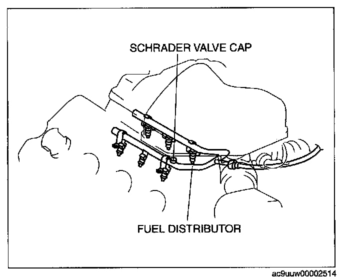
6. Connect a long hose to the disconnected schrader valve cap and drain the fuel into a container used for collecting gasoline.
7. Start the fuel pump using the following procedure.
Using M-MDS
1. Connect the negative battery cable.
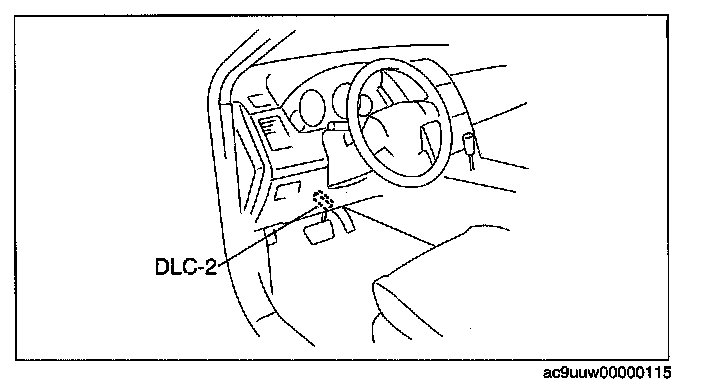
2. Connect the M-MDS to the DLC-2.
3. Using the simulation function "FP", start the fuel pump.
Without using M-MDS
1. Insert a flathead screwdriver into tab part of the check connector and remove the check connector cap.
CAUTION: Connecting to the wrong check connector terminal may only to cause malfunction. Carefully connect the specified terminal.
2. Using a jumper wire, short the following check connector terminals.
- Terminal A and terminal C
- Terminal E and body ground
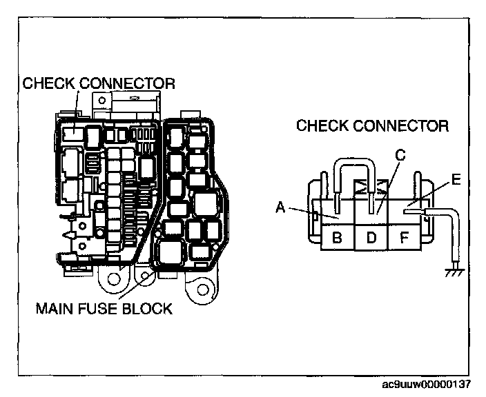
3. Connect the negative battery cable.
4. Turn the ignition switch to ON position to operate the fuel pump.
CAUTION: The fuel pump could be damaged if it is operated (fuel pump idling) while there is no fuel in the fuel tank. Verify the amount of fuel being discharged from the hose and stop operation of the fuel pump when essentially no fuel is being discharged.
8. When essentially no fuel is being discharged, stop operation of the fuel pump.
9. Disconnect the negative battery cable.
10. Remove the following parts.
1. Second-row seat (RH)
2. Edge cover
3. Long slider cover
4. Rear heat duct No.4
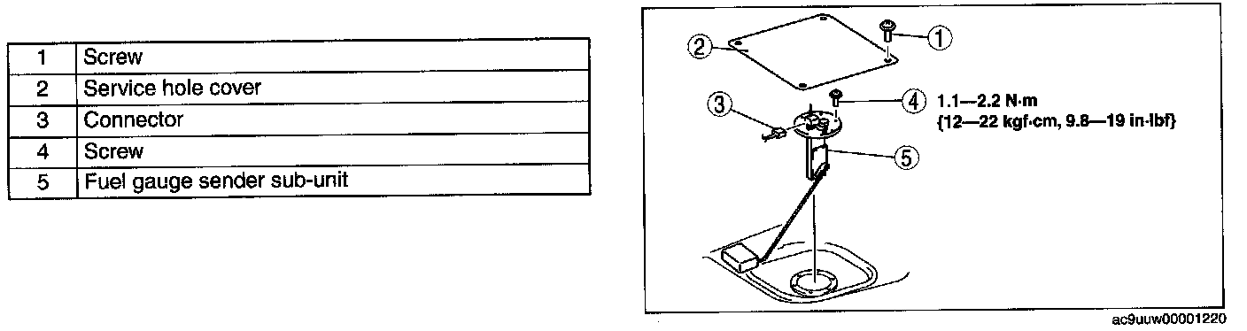
11. Remove in the order indicated in the table.
12. Install in the reverse order of removal.
13. Complete the "AFTER REPAIR PROCEDURE".