Axle Rear (Limited Slip) Removal / Installation
- Remove the axle shaft; See
AXLE SHAFT REAR (LIMITED SLIP) REMOVAL / INSTALLATION
.
- Mark the propeller shaft flange and rear axle companion flange for correct alignment during installation.
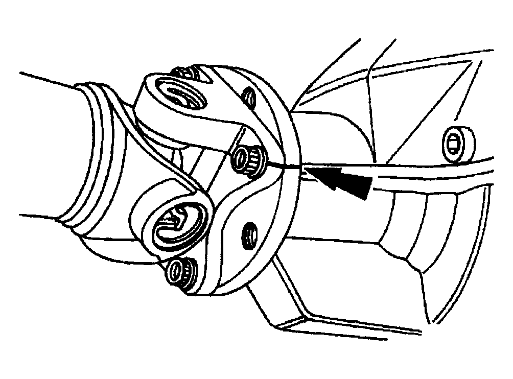 Courtesy of MAZDA MOTORS CORP.
- Remove the four propeller shaft retainer bolts.
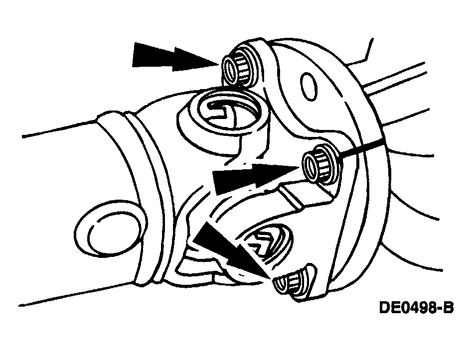 Courtesy of MAZDA MOTORS CORP.
CAUTION:
- The propeller shaft centering yoke fits tightly on the rear axle companion flange pilot. Never hammer on the propeller shaft or any of its components to disconnect the yoke from the flange. Pry only in the area shown with a suitable tool to disconnect the yoke from the flange.
- Using a suitable tool as shown, disconnect the propeller shaft centering socket yoke from the rear axle companion flange.
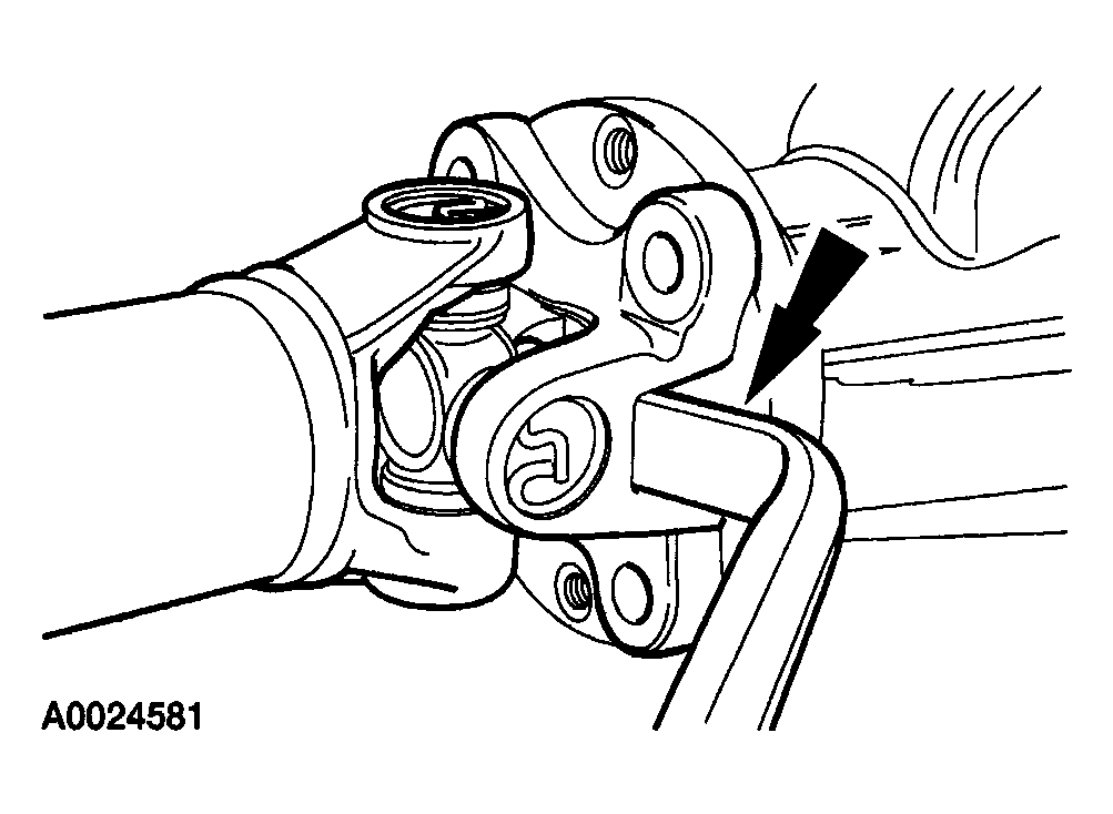 Courtesy of MAZDA MOTORS CORP.
- Disconnect the rear anti-lock brake speed sensor connector and wiring harness clips.
- Separate the wiring harness from the clips and position the harness aside.
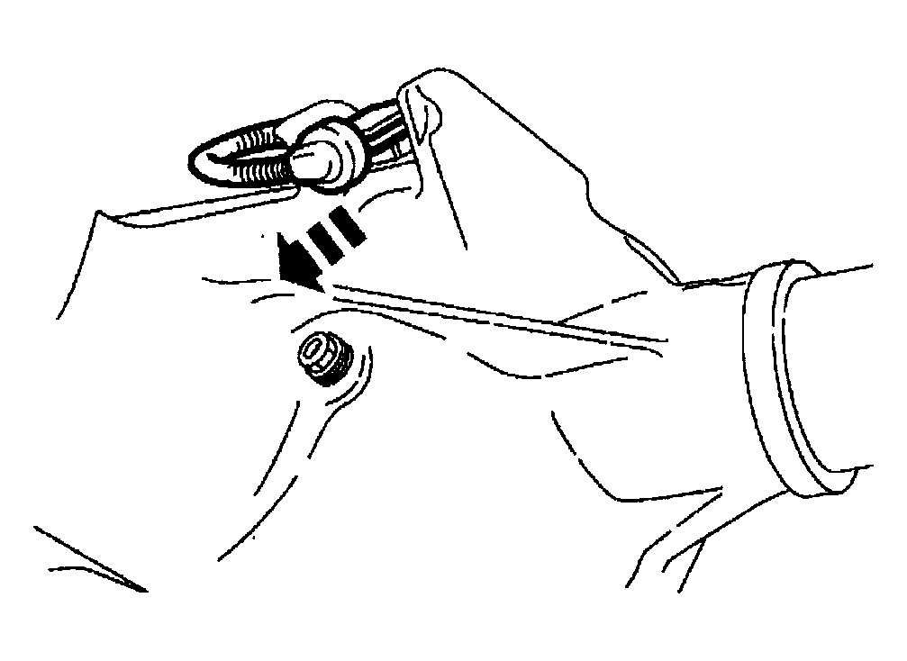 Courtesy of MAZDA MOTORS CORP.
NOTE:
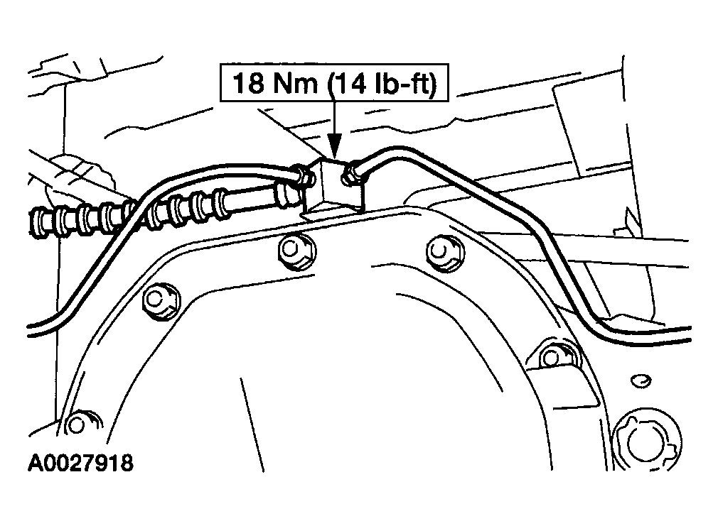
- Do not disconnect the brake lines from the brake hose junction.
- Disconnect the brake hose junction block from the rear axle housing.
 Courtesy of MAZDA MOTORS CORP.
- Disconnect the rear axle vent hose from the rear axle housing.
CAUTION:
- Pull the brake lines from the retaining clips.
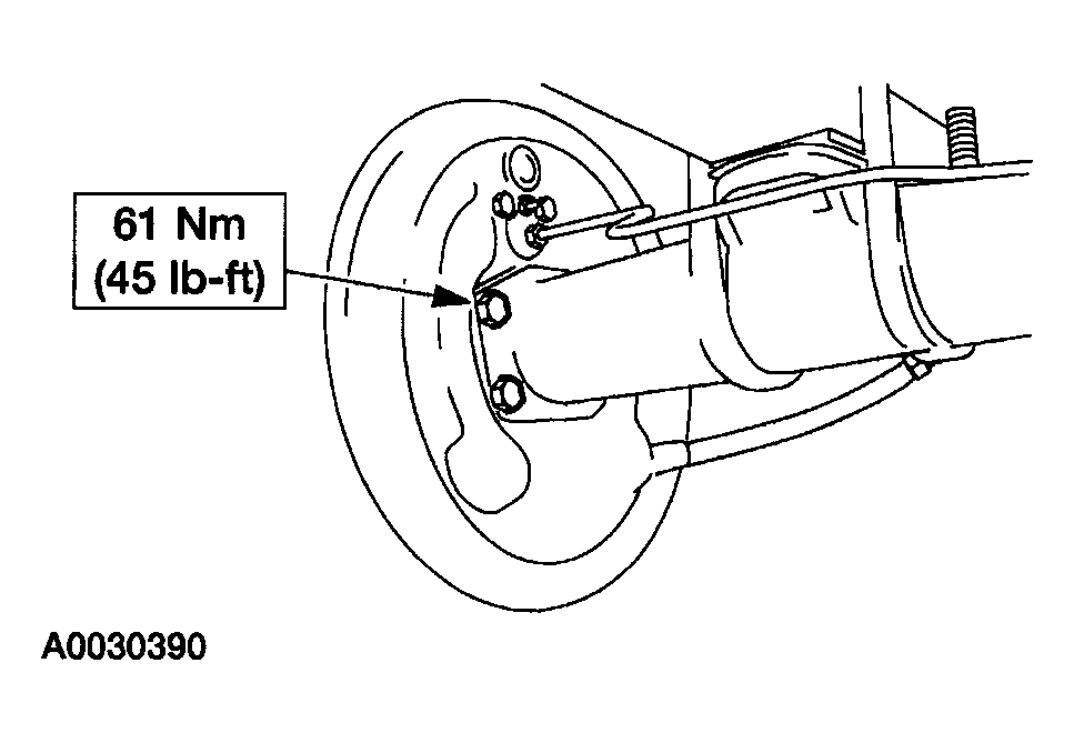
- Disconnect the rear brake drum backing plates and wire them out of the way.
 Courtesy of MAZDA MOTORS CORP.
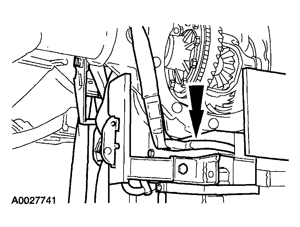
- Position a suitable jack under the rear axle housing and strap it securely in place.
 Courtesy of MAZDA MOTORS CORP.
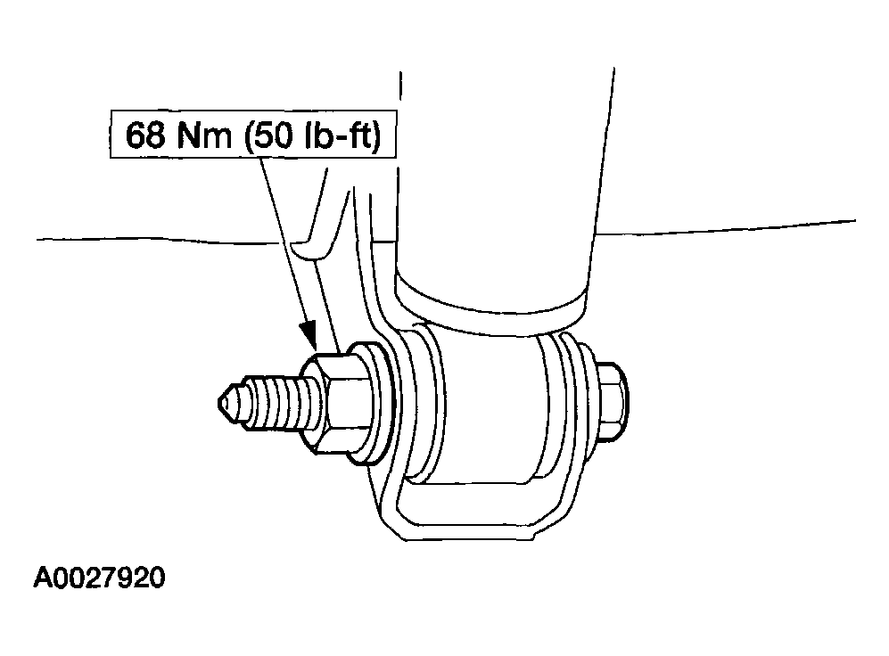
- Remove the nuts and bolts retaining the shock absorbers to the axle.
 Courtesy of MAZDA MOTORS CORP.
- Remove the nuts, the rear axle U-bolts and the rear spring plates.
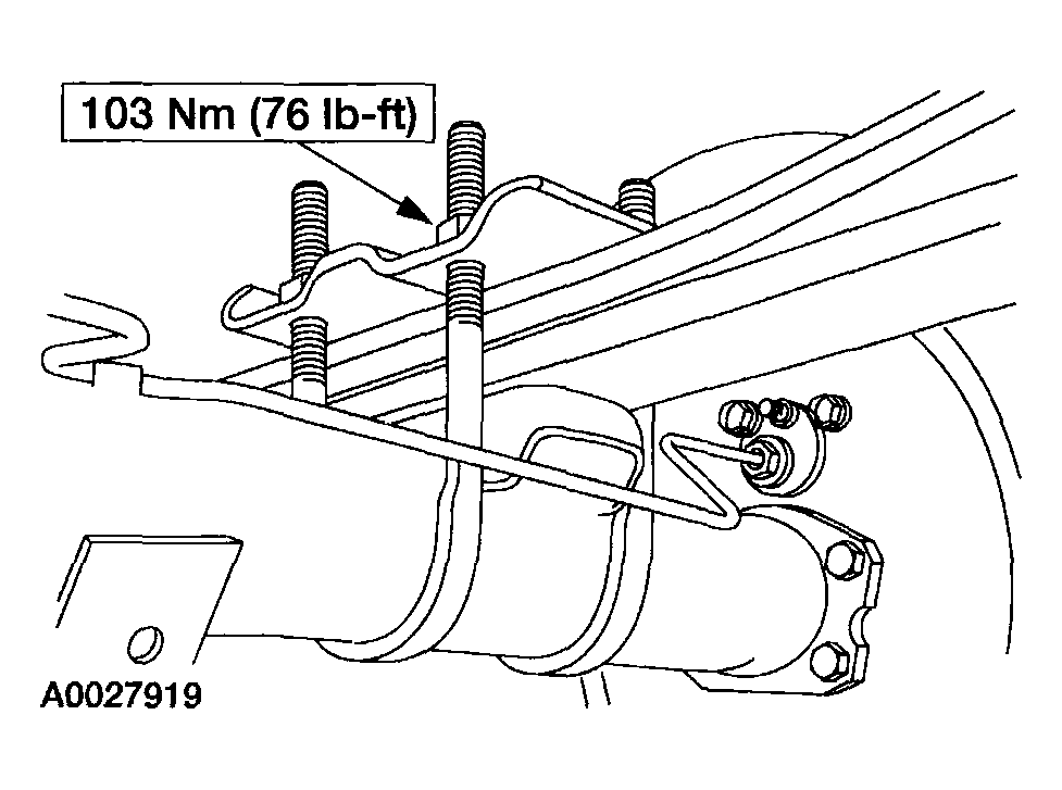 Courtesy of MAZDA MOTORS CORP.
- Lower the rear axle from the vehicle.
CAUTION:
- If new bolts to retain the propeller shaft to the rear axle are not available, coat the original bolts with threadlock.
CAUTION:
- The propeller shaft centering socket yoke fits tightly on the rear axle pinion flange pilot. To make sure that the yoke seats squarely on the flange, tighten the bolts evenly in a cross pattern as shown.
- To install, reverse the removal procedure.