Supplemental Restraint System Deactivation and Reactivation
SUPPLEMENTAL RESTRAINT SYSTEM (SRS) DEACTIVATION AND REACTIVATIONDeactivation
WARNING: Always wear safety glasses when repairing an air bag supplemental restraint system (SRS) vehicle and when handling an air bag module. This will reduce the risk of injury in the event of an accidental deployment.
WARNING: After deployment, the air bag surface can contain deposits of sodium hydroxide, a product of the gas generant combustion that is irritating to the skin. Wash your hands with soap and water afterwards. Failure to follow these instructions may result in personal injury.
WARNING: Never probe the connectors on the air bag module. Doing so can result in air bag deployment, which can result in personal injury.
WARNING: Never probe the connectors on the safety canopy module. Doing so can result in safety canopy deployment, which can result in personal injury.
WARNING: The safety belt pretensioner is a pyrotechnic device. Always wear safety glasses when repairing an air bag equipped vehicle and when handling a safety belt buckle pretensioner or safety belt retractor pretensioner. Never probe a pretensioner electrical connector. Doing so could result in pretensioner or air bag deployment and could result in personal injury.
WARNING: To reduce the risk of personal injury, do not use any memory saver devices.
NOTE: If a seat equipped with an SRS component is being serviced, the SRS must be depowered.
NOTE: After diagnosing or repairing an SRS, the restraint system diagnostic tools must be removed before operating the vehicle over the road.
NOTE: The air bag warning lamp illuminates when the restraints control module (RCM) fuse is removed and the ignition switch is ON. This is normal operation and does not indicate a SRS fault.
NOTE: The SRS must be fully operational and free of faults before releasing the vehicle to the customer.
All vehicles
1. Turn all vehicle accessories OFF.
2. Turn the ignition switch to OFF.
3. At the smart junction box (SJB), located at the RH side of the center console, remove the cover and the RCM fuse 33 (15 A) from the CJB. See the Tribute Wiring Diagram for schematic information.
4. Turn the ignition ON and visually monitor the air bag indicator for at least 30 seconds. The air bag indicator will remain lit continuously (no flashing) if the correct RCM fuse has been removed. If the air bag indicator does not remain lit continuously, remove the correct RCM fuse before proceeding.
5. Turn the ignition OFF.
WARNING: To avoid accidental deployment and possible personal injury, the backup power supply must be depleted before repairing or replacing any front or side air bag SRS components and before servicing, replacing, adjusting or striking components near the front or side air bag sensors, such as doors, instrument panel, console, door latches, strikers, seats and hood latches.
The front impact severity sensor is located on the radiator support bracket.
The first row side impact sensors (if equipped) are located at or near the base of the B-pillars.
The second row side impact sensors (if equipped) are located on the C-pillar.
To deplete the backup power supply energy, disconnect the battery ground cable and wait at least one minute. Be sure to disconnect auxiliary batteries and power supplies (if equipped).
6. Disconnect the battery ground cable and wait at least one minute.
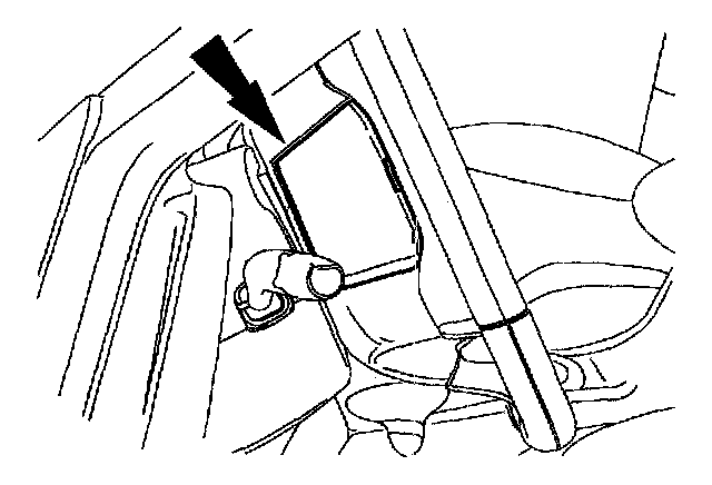
7. Remove the steering wheel access cover.
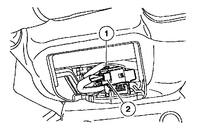
8. Disconnect the driver air bag module electrical connector.
1. Through the steering wheel access cover opening, release the pin-type retainer and slide the driver air bag module electrical connector off of the pin-type retainer.
2. Release the tab and disconnect the driver air bag module electrical connector.
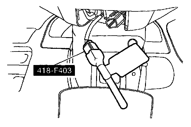
9. Attach the restraint system diagnostic tool to the clockspring electrical connector at the top of the steering column.
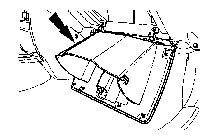
10. Open the glove compartment door past its stops.
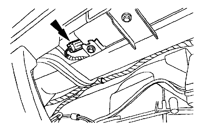
11. Through the glove compartment opening, disconnect the passenger air bag module electrical connector.
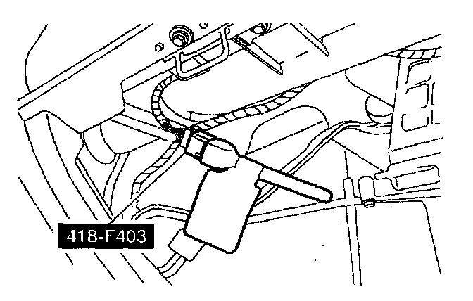
12. Attach the restraint system diagnostic tool to the vehicle harness side of the passenger air bag module electrical connector.
Vehicles with safety canopies and seat side air bags
NOTE: If the headliner near each B-pillar has the word AIRBAG embossed on it, the vehicle is equipped with safety canopy modules and seat side air bags.
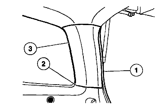
13. Remove the passenger side D-pillar trim panel.
1. Separate the weatherstrip.
2. Pull out and separate the quarter trim panel at the D-pillar trim panel.
3. Pull out to release the retainers and remove the D-pillar trim panel.
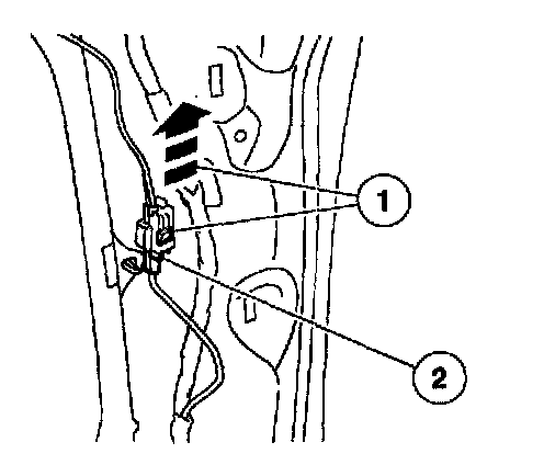
14. Disconnect the passenger side safety canopy module electrical connector.
1. Slide and disengage the passenger side safety canopy module electrical connector locking clip.
2. Push in to release the tab and disconnect the passenger side safety canopy module electrical connector.
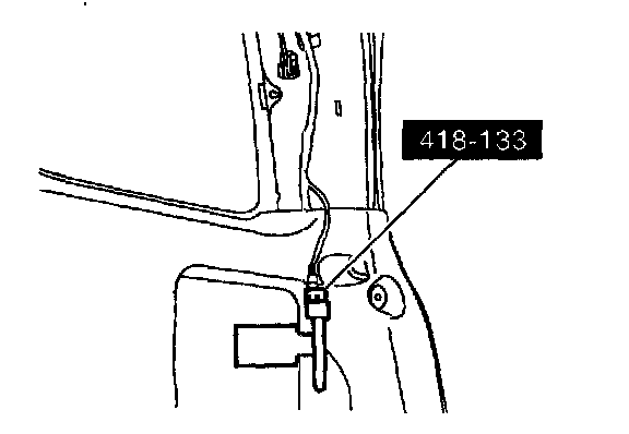
15. Attach the restraint system diagnostic tool to the vehicle harness side of the passenger side safety canopy module electrical connector.
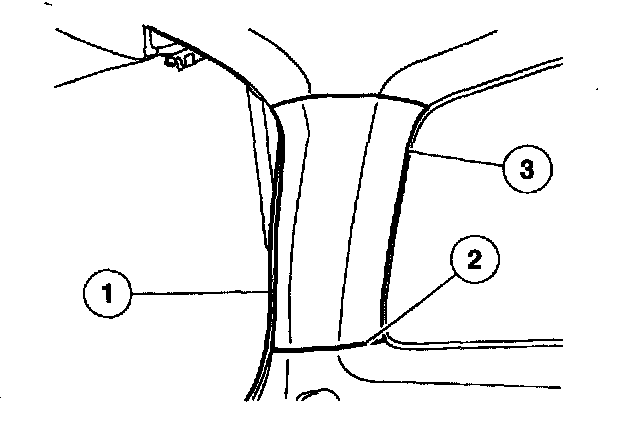
16. Remove the driver side D-pillar trim panel.
1. Separate the weatherstrip.
2. Pull out and separate the quarter trim panel at the D-pillar trim panel.
3. Pull out to release the retainers and remove the D-pillar trim panel.
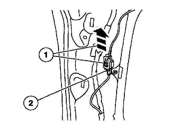
17. Disconnect the driver side safety canopy module electrical connector.
1. Slide and disengage the driver side safety canopy module electrical connector locking clip.
2. Push in to release the tab and disconnect the driver side safety canopy module electrical connector.
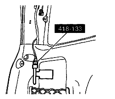
18. Attach the restraint system diagnostic tool to the vehicle harness side of the driver side safety canopy module electrical connector.
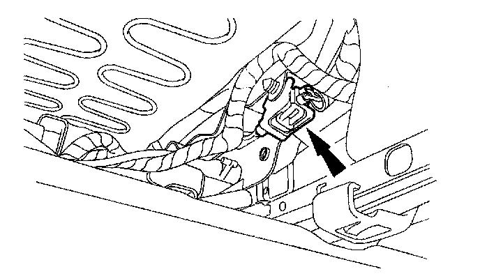
19. From under the rear of the passenger seat, slide and disengage the passenger seat side air bag module electrical connector locking clip, and then release the tab and disconnect the passenger seat side air bag module electrical connector.
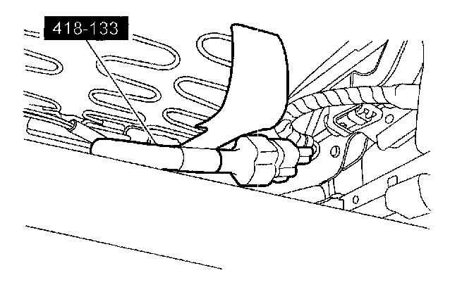
20. Attach the restraint system diagnostic tool to the vehicle harness side of the passenger seat side air bag module electrical connector.
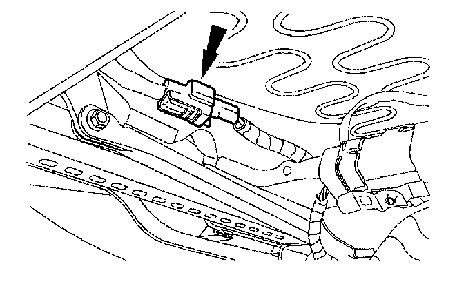
21. From under the rear of the driver seat, slide and disengage the driver seat side air bag module electrical connector locking clip, and then release the tab and disconnect the driver seat side air bag module electrical connector.
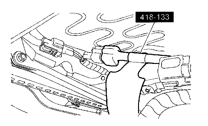
22. Attach the restraint system diagnostic tool to the vehicle harness side of the driver seat side air bag module electrical connector.
All vehicles
23. Install the RCM fuse 33 (15 A) to the SJB.
24. Connect the battery ground cable.
Reactivation
All vehicles
1. Remove the RCM fuse 33 (15 A) from the SJB.
2. Disconnect the battery ground cable and wait at least one minute.
Vehicles with safety canopies and seat side air bags
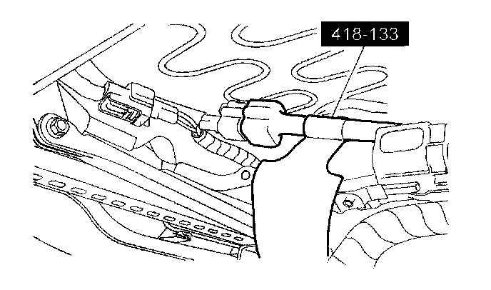
3. Remove the restraint system diagnostic tool from the vehicle harness side of the driver seat side air bag module electrical connector.
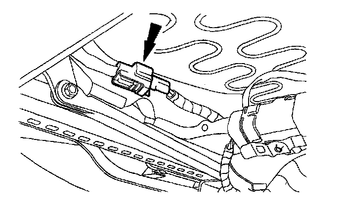
4. Connect the driver seat side air bag module electrical connector and then slide and engage the seat side air bag electrical connector locking clip.
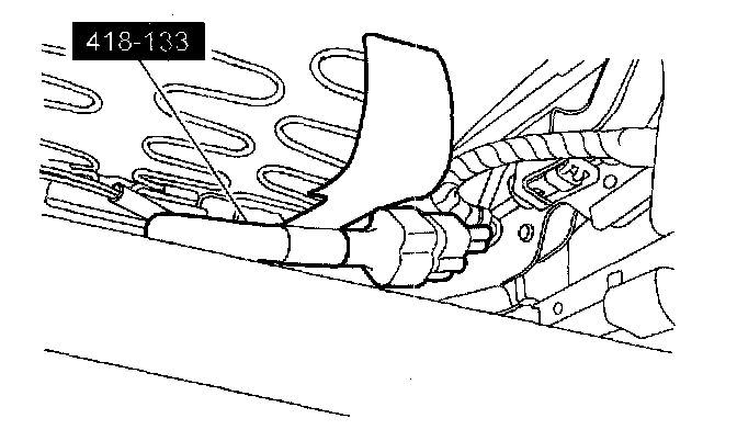
5. Remove the restraint system diagnostic tool from the vehicle harness side of the passenger seat side air bag module electrical connector.
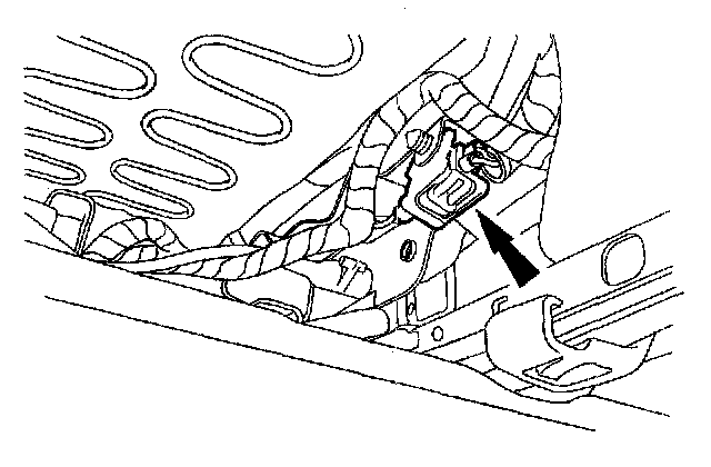
6. Connect the passenger seat side air bag module electrical connector and then slide and engage the seat side air bag electrical connector locking clip.
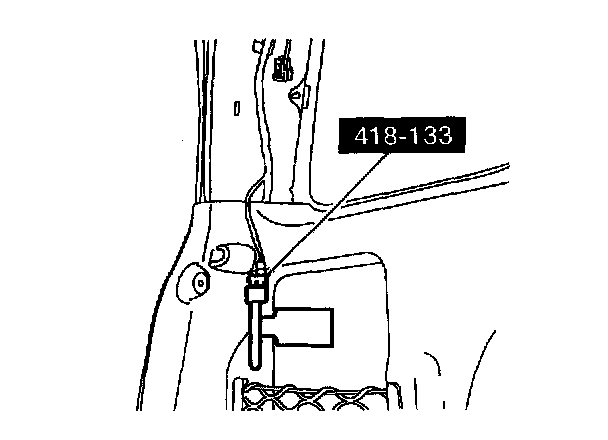
7. Remove the restraint system diagnostic tool from the vehicle harness side of the driver side safety canopy module electrical connector.
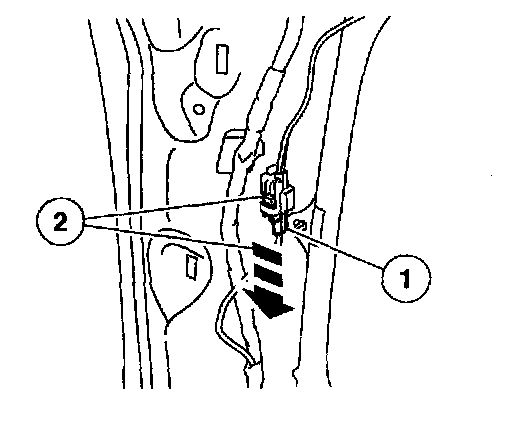
8. Connect the driver side safety canopy module electrical connector.
1. Connect the driver side safety canopy module electrical connector.
2. Slide and engage the driver side safety canopy module electrical connector locking clip.
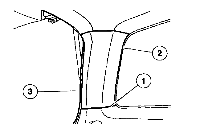
9. Install the driver side D-pillar trim panel.
1. Engage the D-pillar trim panel to the quarter trim panel.
2. Install the D-pillar trim panel.
3. Install the weatherstrip.
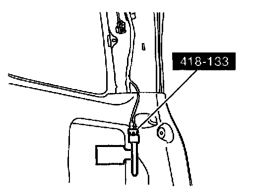
10. Remove the restraint system diagnostic tool from the vehicle harness side of the passenger side safety canopy module electrical connector.
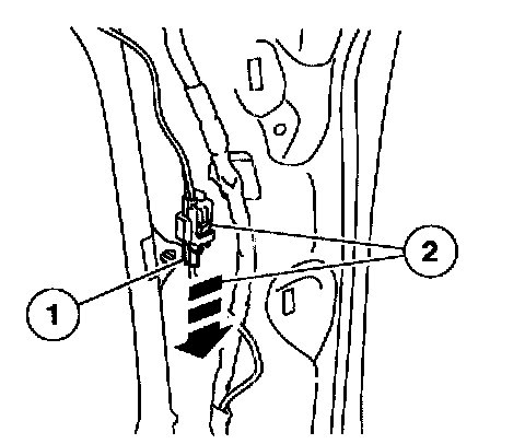
11. Connect the passenger side safety canopy module electrical connector.
1. Connect the passenger side safety canopy module electrical connector.
2. Slide and engage the passenger side safety canopy module electrical connector locking clip.
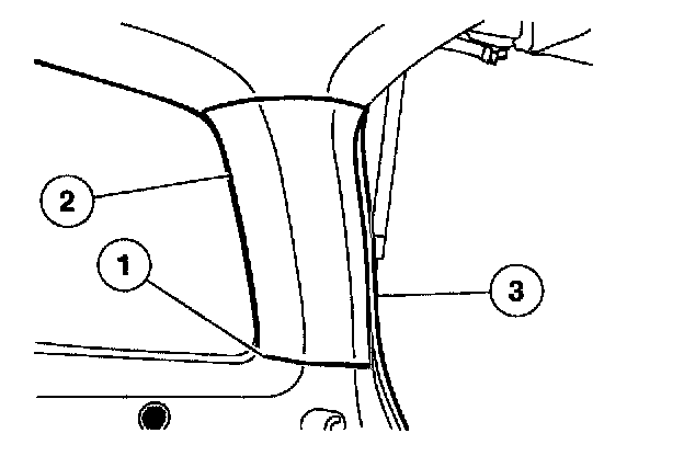
12. Install the passenger side D-pillar trim panel.
1. Engage the D-pillar trim panel to the quarter trim panel.
2. Install the D-pillar trim panel.
3. Install the weatherstrip. All vehicles
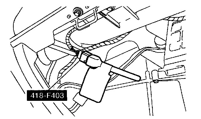
13. Remove the restraint system diagnostic tool from the vehicle harness side of the passenger air bag module electrical connector.
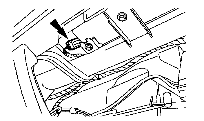
14. Through the glove compartment opening, connect the passenger air bag module electrical connector.
15. Close the glove compartment.
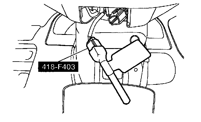
16. Remove the restraint system diagnostic tool from the clockspring electrical connector at the top of the steering column.
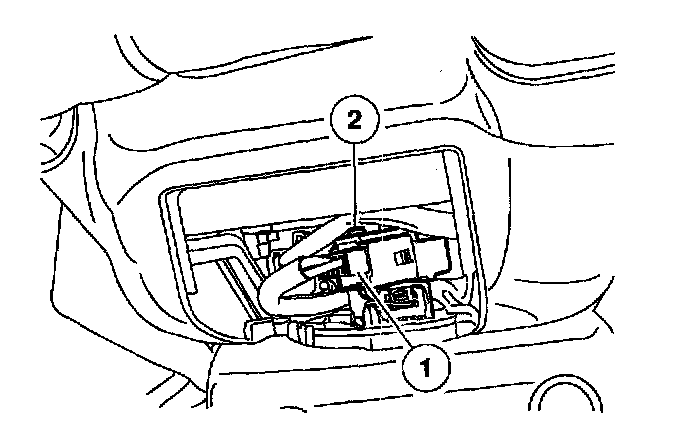
17. Connect and install the driver air bag module electrical connector.
1. Connect the driver air bag module electrical connector.
2. Through the steering wheel access cover opening, slide the driver air bag module electrical connector onto the pin-type retainer.
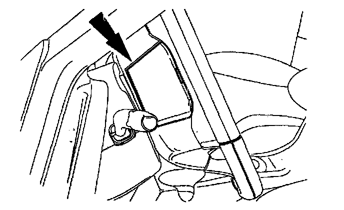
18. Install the steering wheel access cover.
WARNING: The restraint system diagnostic tool is for restraint system service only. Remove from vehicle prior to road use. Failure to remove could result in injury and possible violation of vehicle safety standards.
19. Make sure all restraint system diagnostic tool(s) that may have been installed during the repair have been removed from the vehicle and all SRS components are connected.
20. Turn the ignition switch from OFF to ON.
21. Install RCM fuse 33 (15 A) to the SJB and install the cover.
WARNING: Be sure that nobody is in the vehicle and that there is nothing blocking or set in front of any air bag module when the battery ground cable is connected. Failure to follow these instructions may result in personal injury.
22. Connect the battery ground cable.
23. Prove out the SRS as follows:
Turn the ignition key from ON to OFF. Wait 10 seconds, then turn the key back to ON and visually monitor the air bag indicator with the air bag modules installed. The air bag indicator will light continuously for approximately 6 seconds and then turn off. If an air bag SRS fault is present, the air bag indicator will:
- fail to light
- remain lit continuously
- flash
The flashing might not occur until approximately 30 seconds after the ignition switch has been turned from the OFF to the ON position. This is the time required for the restraints control module (RCM) to complete the testing of the SRS. If the air bag indicator is inoperative and a SRS fault exists, a chime will sound in a pattern of 5 sets of 5 beeps. If this occurs, the air bag indicator and any SRS fault discovered must be diagnosed and repaired. Clear all continuous DTCs from the restraints control module using a diagnostic tool.