Intake Manifold Removal / Installation - 4.0L
 Courtesy of MAZDA MOTORS CORP.
 Courtesy of MAZDA MOTORS CORP.
 Courtesy of MAZDA MOTORS CORP.
 Courtesy of MAZDA MOTORS CORP.
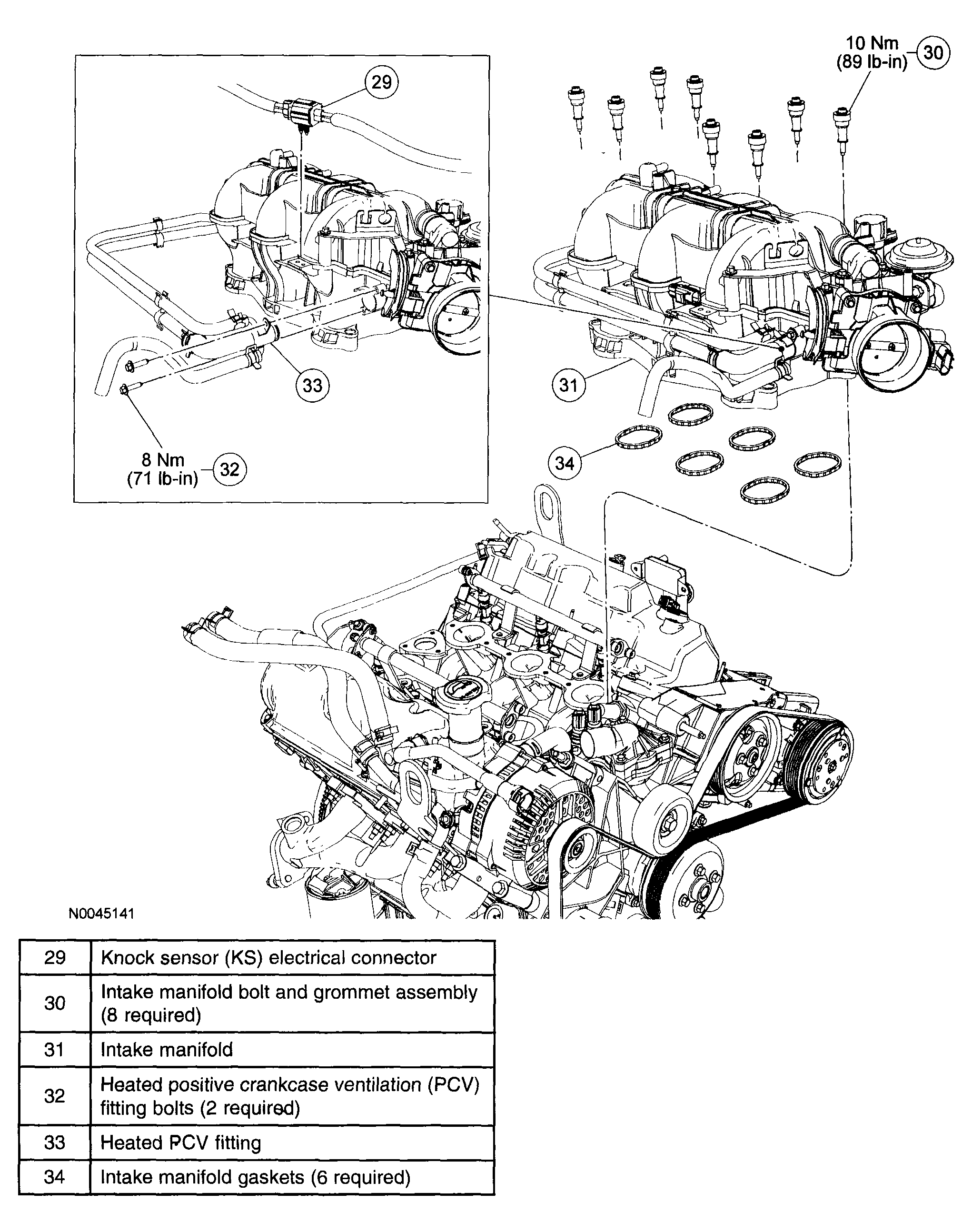 Courtesy of MAZDA MOTORS CORP.
- Disconnect the negative battery cable. See
BATTERY DISCONNECT
,
.
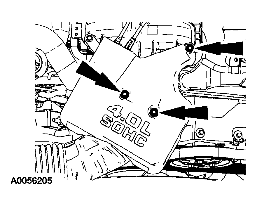 Courtesy of MAZDA MOTORS CORP.
- Remove the accelerator control splash shield.
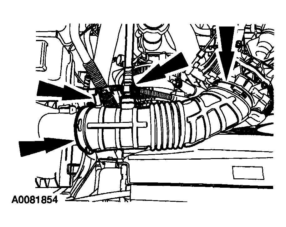 Courtesy of MAZDA MOTORS CORP.
- Remove the air cleaner outlet pipe.
- Disconnect the tube.
- Detach the mass airflow (MAF) sensor wiring pin-type retainer.
- Loosen the clamps and remove the pipe.
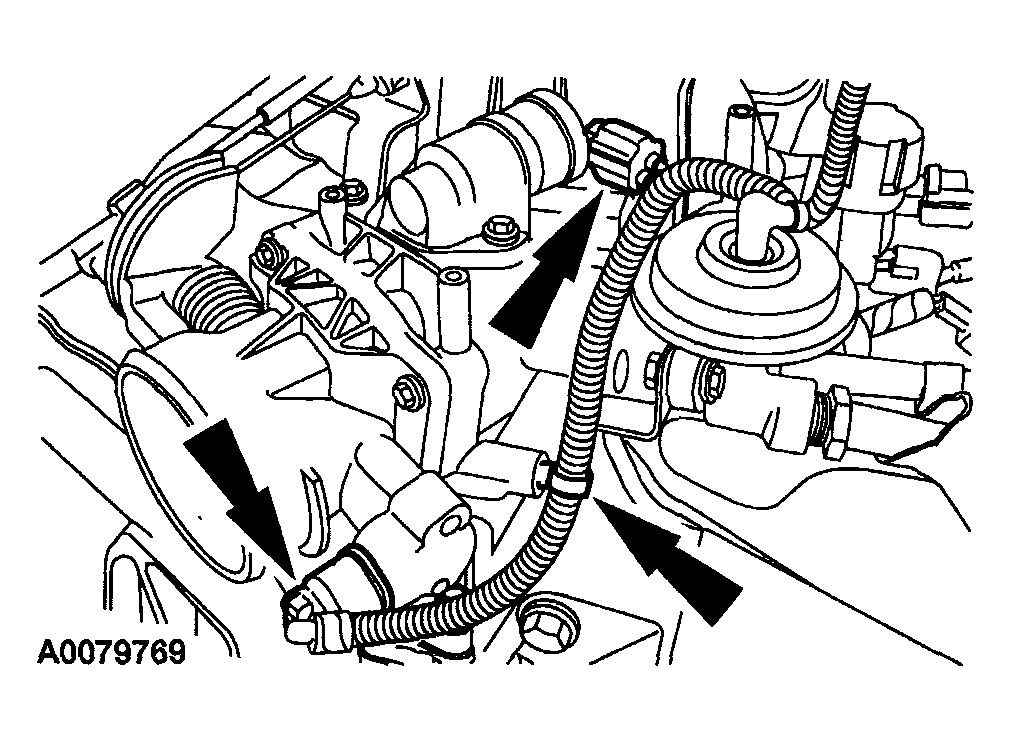 Courtesy of MAZDA MOTORS CORP.
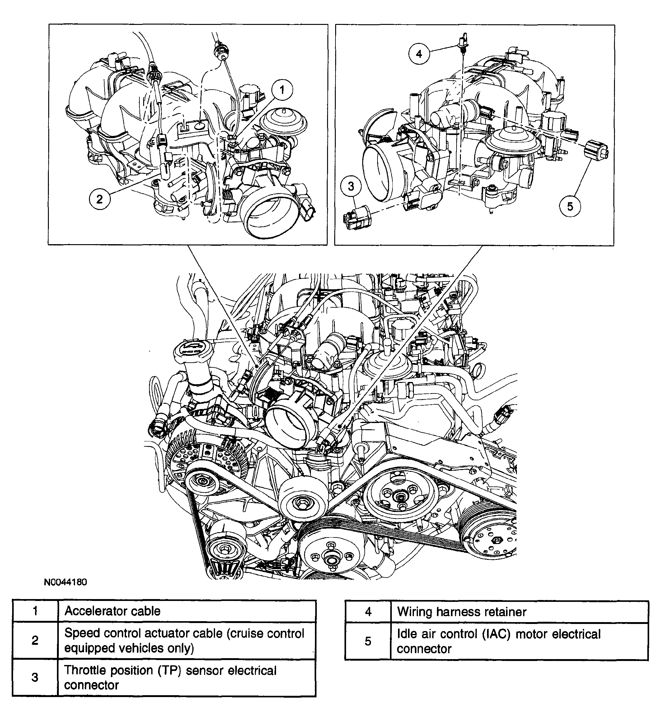
- Disconnect the idle air control (IAC) valve, throttle position (TP) sensor electrical connectors and the TP sensor wiring pin-type retainer.
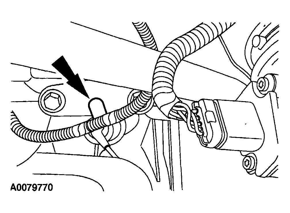 Courtesy of MAZDA MOTORS CORP.
- Disconnect the MAF sensor wiring pin-type retainer.
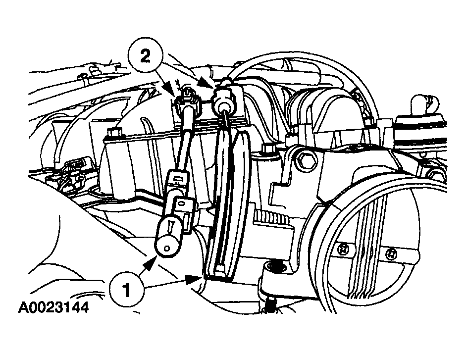 Courtesy of MAZDA MOTORS CORP.
- Disconnect the accelerator and cruise control cables.
- Detach the accelerator and cruise control cables from the throttle body.
- Detach the accelerator and cruise control cables from the bracket, and position the cables aside.
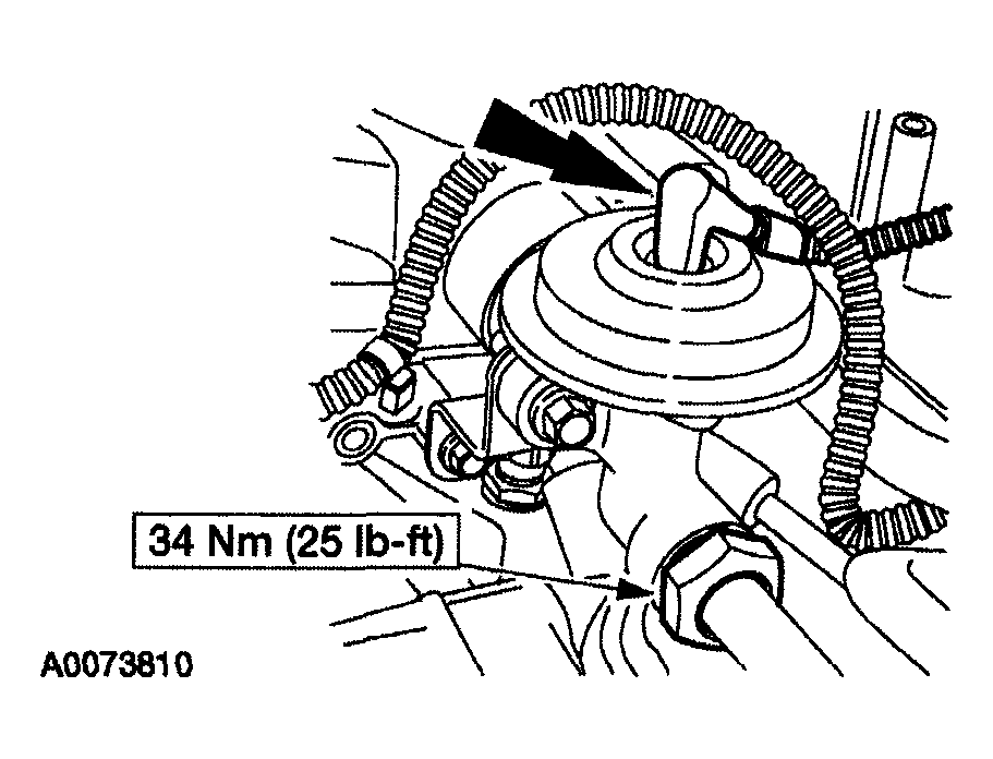 Courtesy of MAZDA MOTORS CORP.
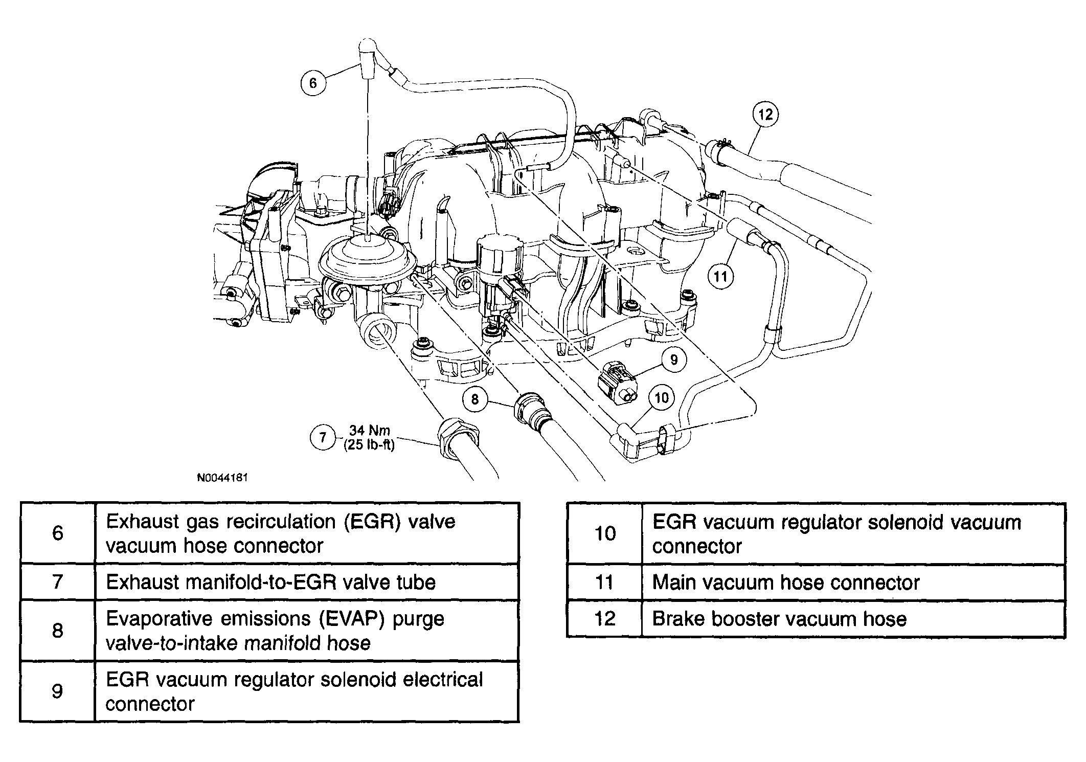
- Disconnect the exhaust gas recirculation (EGR) valve vacuum hose and tube fitting.
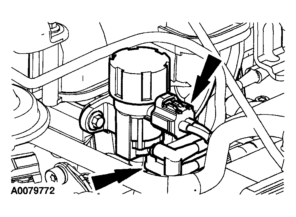 Courtesy of MAZDA MOTORS CORP.
- Disconnect the EGR vacuum regulator solenoid valve electrical connector and vacuum hose.
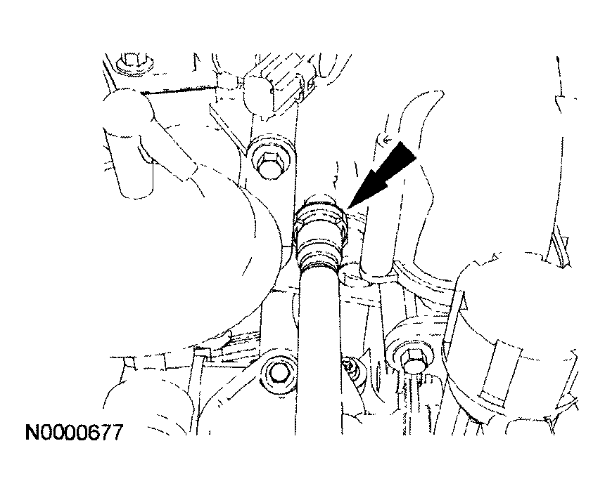 Courtesy of MAZDA MOTORS CORP.
NOTE:
- Late build vehicles shown, early build vehicles similar.
- Disconnect the hose.
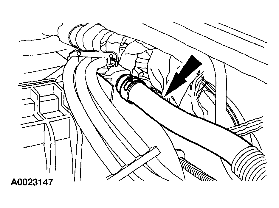 Courtesy of MAZDA MOTORS CORP.
- Loosen the clamp and disconnect the brake booster vacuum hose.
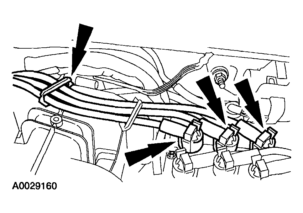 Courtesy of MAZDA MOTORS CORP.
CAUTION:
- It is important to twist the spark plug wire boots while pulling upward to avoid possible damage to the spark plug wire.
NOTE:
- Spark plug wires must be connected to the correct ignition coil terminal. Mark the spark plug wire locations before removing them.
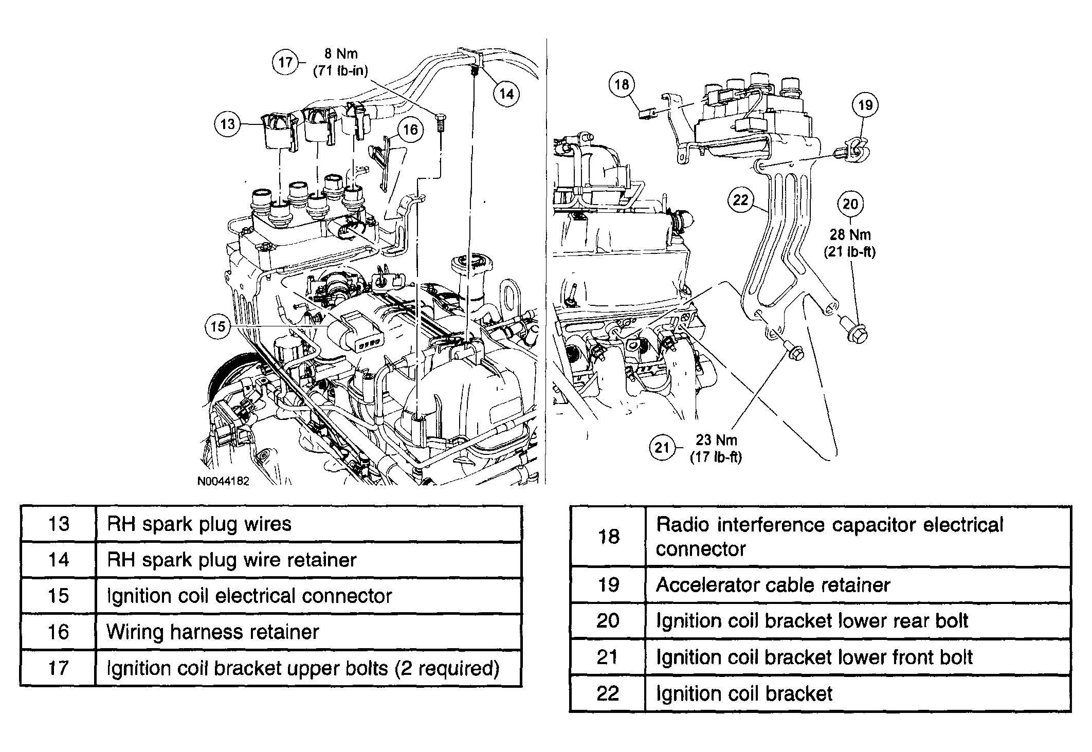
- Disconnect the RH spark plug wires from the coil. Remove the spark plug wire routing clip pin-type retainer and position the wires aside.
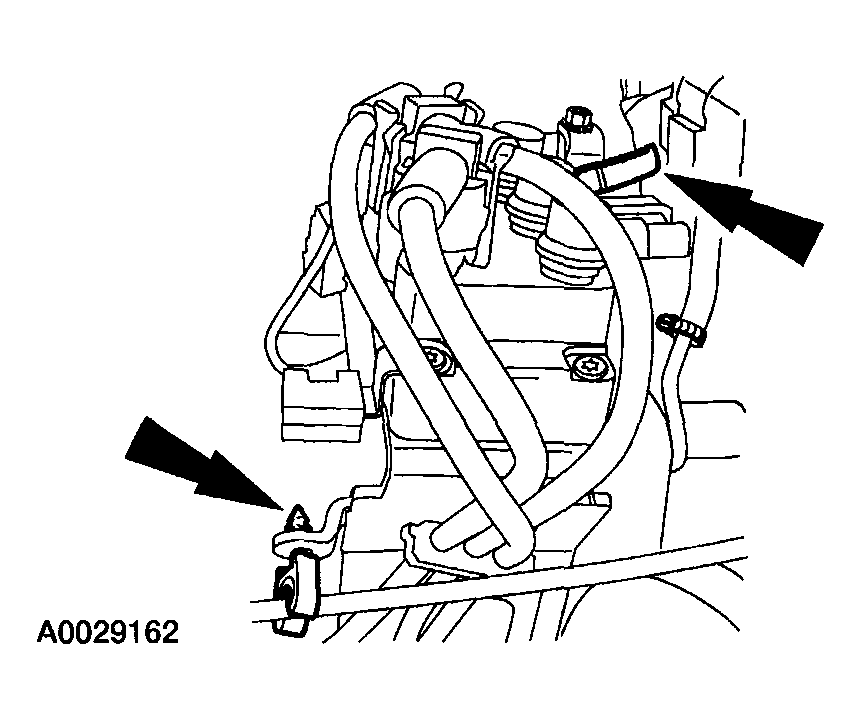 Courtesy of MAZDA MOTORS CORP.
- Remove the accelerator cable routing clip pin-type retainer and the wiring harness pin-type retainer.
 Courtesy of MAZDA MOTORS CORP.
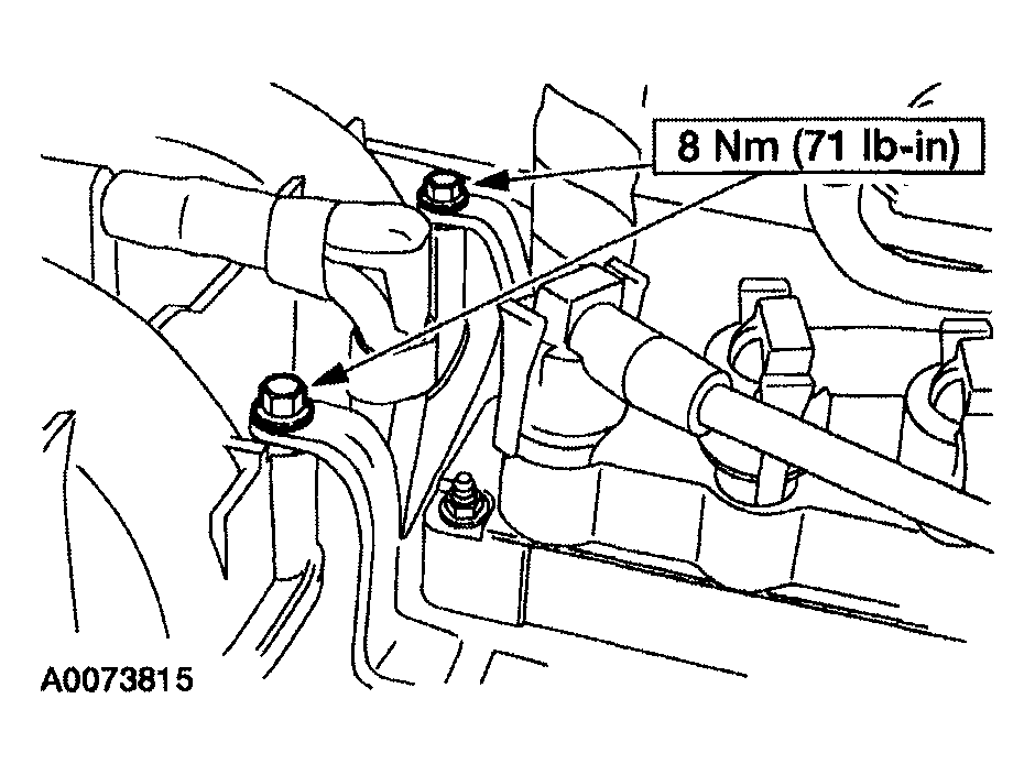
- Remove the bolts.
 Courtesy of MAZDA MOTORS CORP.
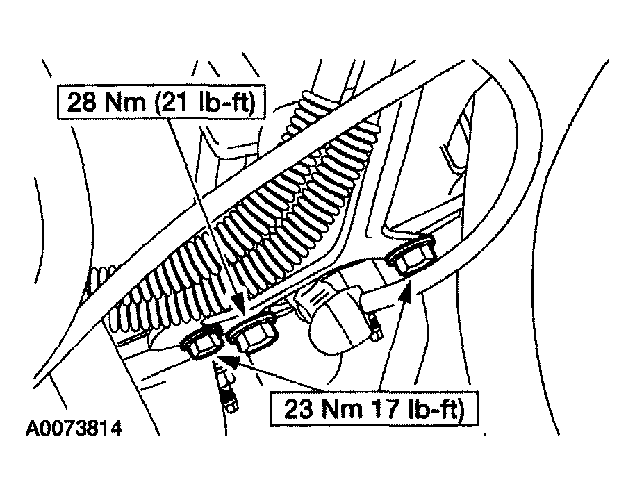
- Remove the bolts and position the coil and bracket aside.
 Courtesy of MAZDA MOTORS CORP.
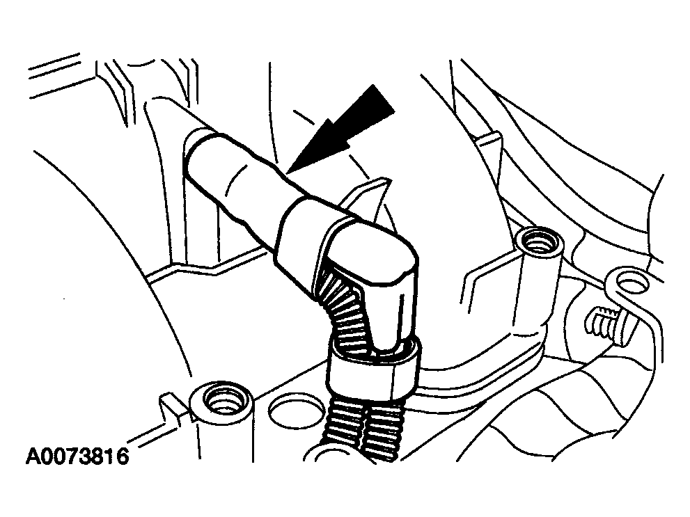
- Disconnect the vacuum hoses.
 Courtesy of MAZDA MOTORS CORP.
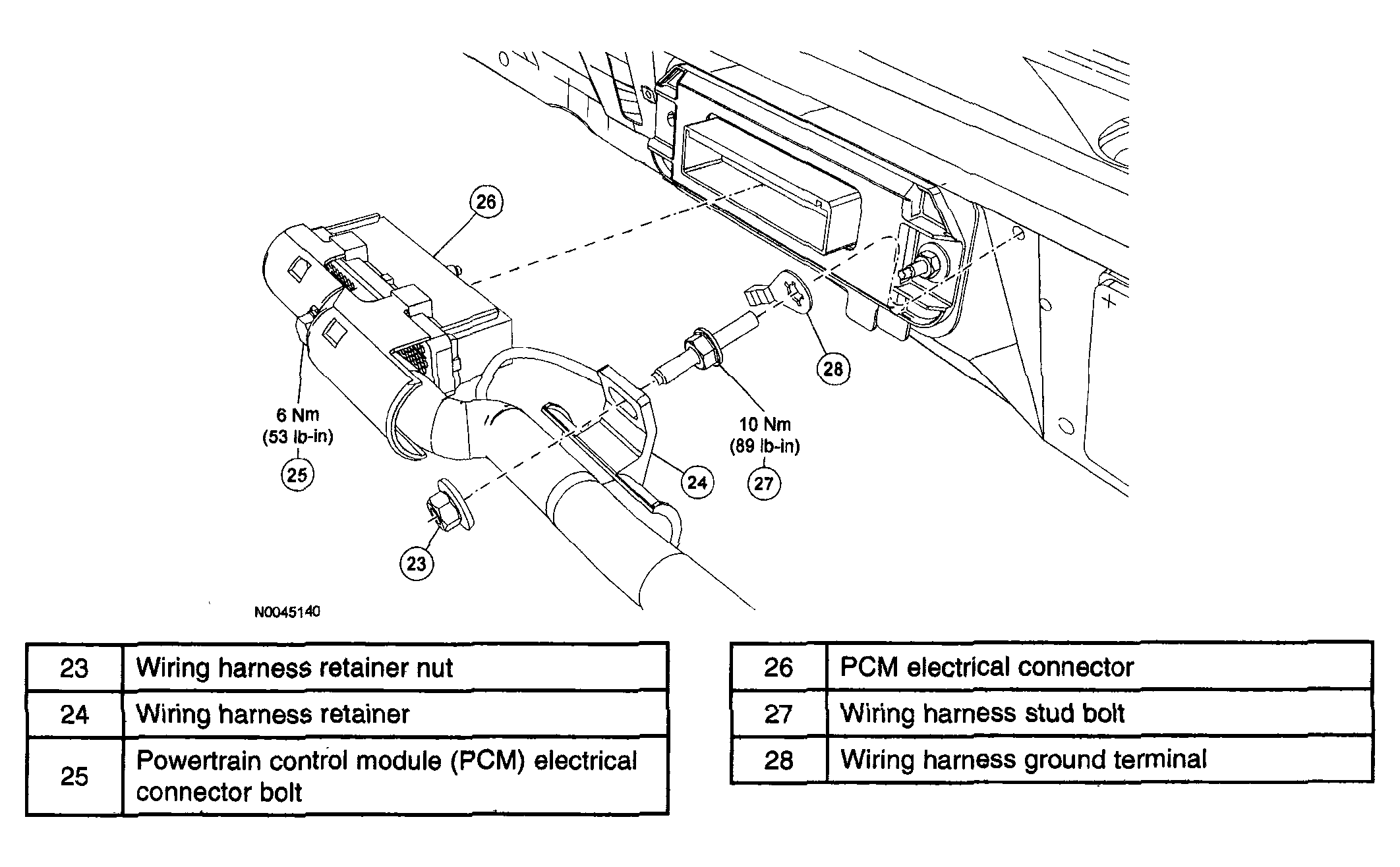
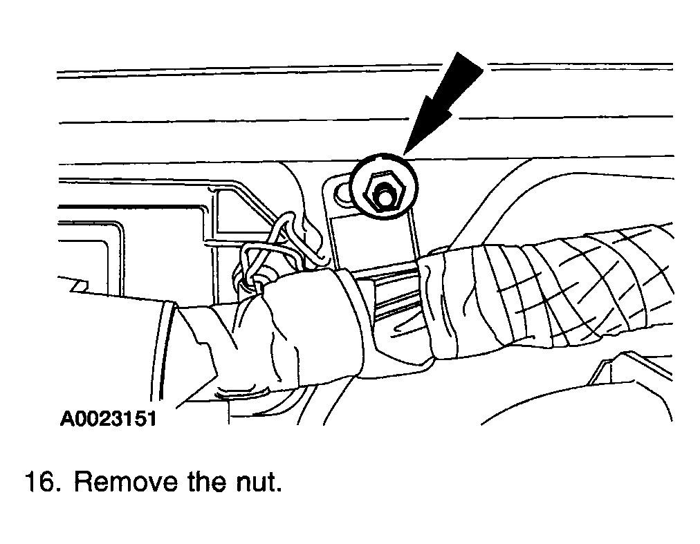
- Remove the nut.
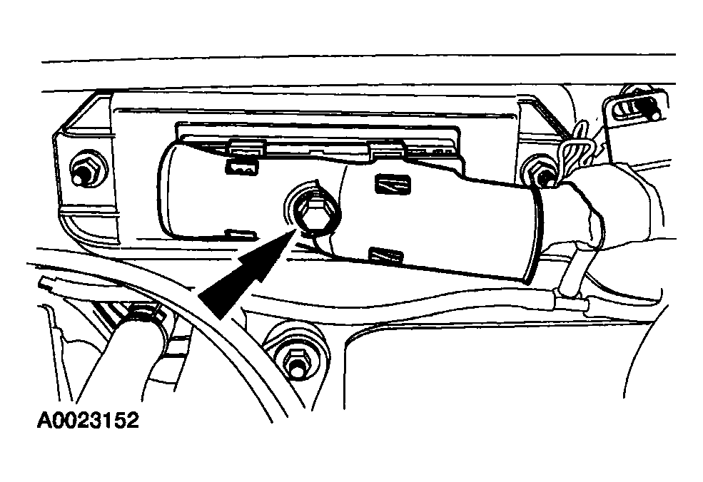 Courtesy of MAZDA MOTORS CORP.
- Disconnect the powertrain control module (PCM) electrical connector.
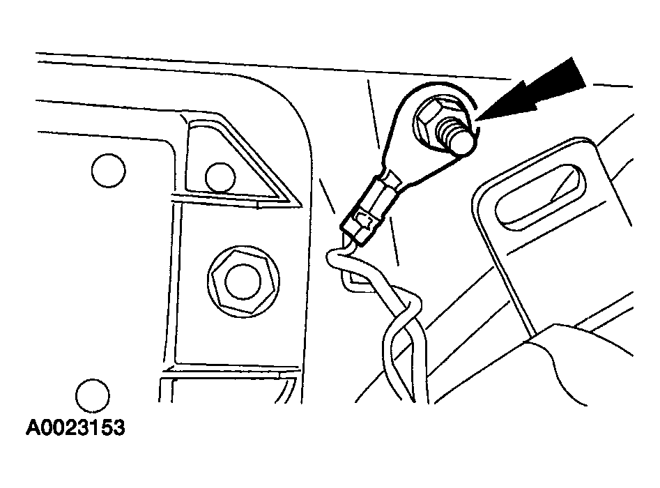 Courtesy of MAZDA MOTORS CORP.
- Remove the retainer and position the ground wires aside.
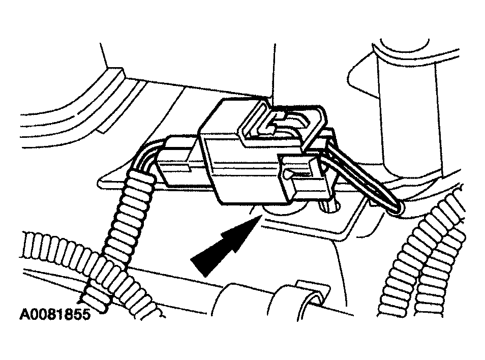 Courtesy of MAZDA MOTORS CORP.
- Detach the electrical connector retainer.
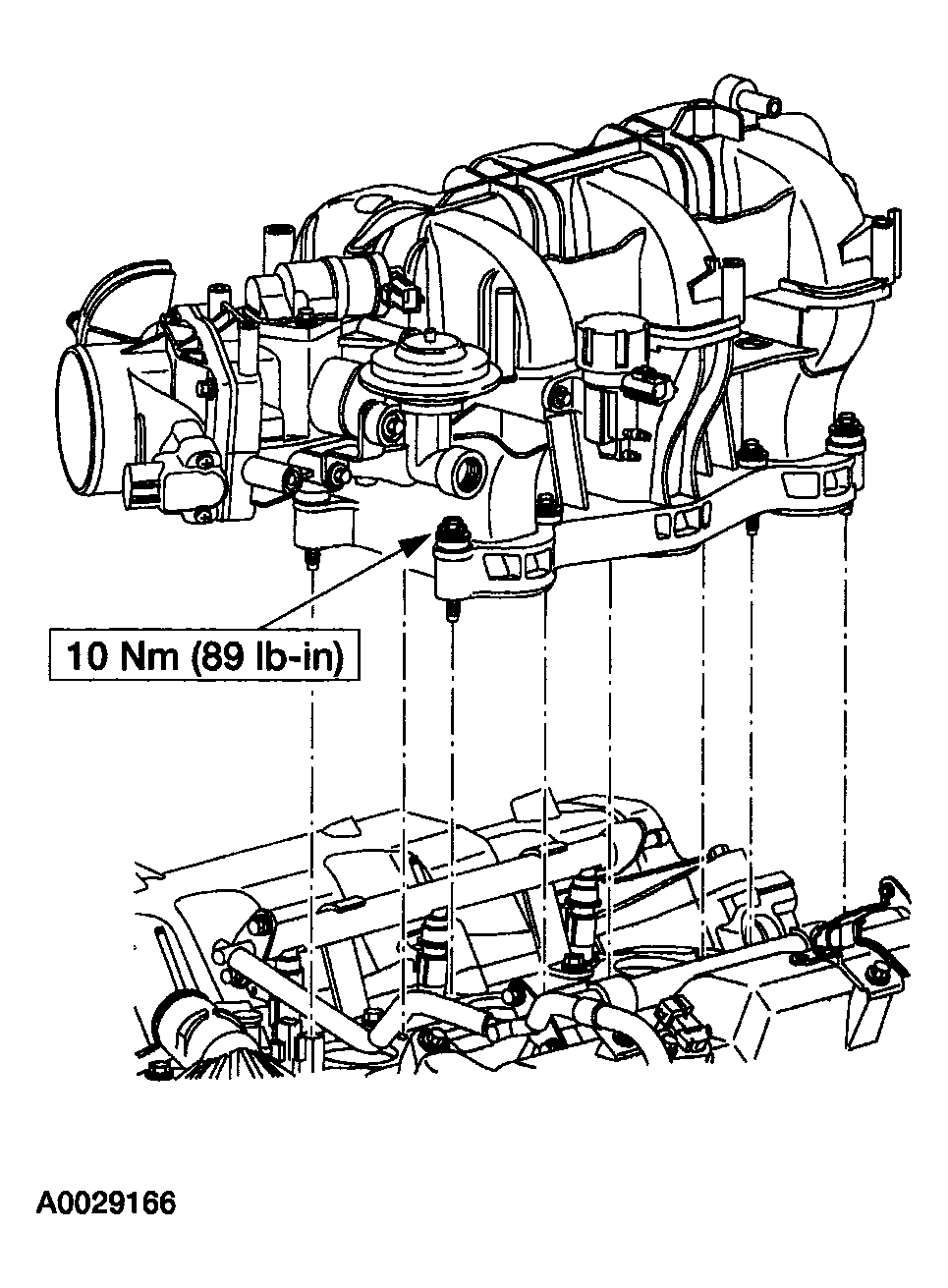 Courtesy of MAZDA MOTORS CORP.
- Remove the intake manifold bolts and lift up the intake manifold.
 Courtesy of MAZDA MOTORS CORP.
- Remove the heated positive crankcase ventilation (PCV) hose retainers and remove the heated PCV fitting.
- Remove the intake manifold.
- To install, reverse the removal procedure.