Diagnostic Procedures
- If QUICK TEST was not performed, go to QUICK TEST under SELF-DIAGNOSTIC SYSTEM. If QUICK TEST was performed, go to next step.
- DTC P1451: Check VPWR Voltage To Canister Vent Solenoid
Turn ignition off. Disconnect CV solenoid. Connect a non-powered test lamp between CV and VPWR circuits at CV solenoid harness connector. Turn ignition on, engine off. Using scan tool, select DIAGNOSTIC DATA LINK. Select PCM. Select PID/DATA MONITOR AND RECORD. Attempt to close and open CV solenoid driver in PCM by accessing OUTPUT TEST MODE. Select ALL OFF mode. Cycle START button ON and OFF, and observe test lamp. If test lamp cycles on and off (light up and turn off), turn ignition off and go to next step. If test lamp is always off, go to step 4. If test lamp is always on, turn ignition off and go to step 8.
- Check CV Solenoid Resistance
Measure CV solenoid resistance. If resistance reading is 45-65 ohms, problem is intermittent. Refer to INTERMITTENT testing under SYSTEM TESTS . If resistance reading is not as specified, replace damaged CV solenoid.
- Check For Open VPWR Circuit Between CV Solenoid & Power Relay
Measure voltage of VPWR circuit (Light Blue/Orange wire) between CV solenoid harness connector and negative battery terminal. See Fig 1. If voltage reading is more than 10.5 volts, turn ignition off and go to next step. If voltage reading is not as specified, repair open in Light Blue/Orange wire between PCM power relay and CV solenoid harness connector. See WIRING DIAGRAMS
article. After repair, go to step 10.
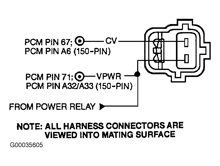 Courtesy of FORD MOTOR CO.
- Check VPWR Circuit For Open In Harness
Disconnect PCM 104-pin harness connector. Connect Breakout Box (49-UN01-130) to PCM harness connector only. See Figure. Measure resistance of VPWR circuit between breakout box terminal No. 71 (White/Red wire) and CV solenoid harness connector (Light Blue/Orange wire). If resistance reading is less than 5.0 ohms, go to next step. If resistance reading is not as specified, repair open circuit between PCM 104-pin harness connector terminal No. 71 (White/Red wire) and CV solenoid harness connector (Light Blue/Orange wire). After repair, go to step 10.
- Check CV Circuit For Open In Harness
Measure resistance of CV circuit between breakout box terminal No. 67 and CV solenoid harness connector (Violet/White wire). See Fig 1. If resistance reading is less than 5.0 ohms, replace PCM. After repair, go to next step. If resistance reading is not as specified, repair open in Violet/White wire between PCM 104-pin harness connector terminal No. 67 and CV solenoid harness connector. See WIRING DIAGRAMS
article. After repair, go to step 10.
- Check CV Circuit For Short To VPWR
Turn ignition on, engine off. Measure voltage of CV circuit between CV solenoid harness connector and ground. If voltage reading is less than one volt, replace PCM. After repair, go to step 10. If voltage reading is one volt or more, repair short to VPWR in Violet/White wire between PCM 104-pin harness connector terminal No. 67 and CV solenoid harness connector. After repair, go to step 10.
- Check CV Circuit For Short To PWR GND In Harness
Disconnect PCM 104-pin harness connector. Disconnect scan tool from DLC. Measure resistance of CV circuit (Violet/White wire) between CV solenoid harness connector and negative battery terminal. See Fig 1. If resistance reading is more than 10,000 ohms, go to next step. If resistance reading is not as specified, repair short in Violet/White wire between PCM 104-pin harness connector terminal No. 67 and CV solenoid harness connector. After repair, go to step 10.
- Check Circuit For Short To Power
Reconnect scan tool. Turn ignition on, engine off. Measure voltage of CV circuit (Violet/White wire) between CV solenoid harness connector and ground. Turn ignition off. If voltage reading was less than one volt, replace PCM. After repair, go to next step. If voltage reading was not less than one volt, repair short to VPWR, VREF or ground in Violet/White wire between PCM 104-pin harness connector terminal No. 67 and CV solenoid harness connector. See WIRING DIAGRAMS
article. After repair, go to next step.
- Verify Trouble Shooting Of DTCs Completed
Reconnect all disconnected connectors. Clear DTCs from PCM memory using scan tool. Perform QUICK TEST under SELF-DIAGNOSTIC SYSTEM. If same DTC is present, replace faulty PCM. Repeat QUICK TEST under SELF-DIAGNOSTIC SYSTEM. If same DTC is not present, go to applicable procedure for other DTCs. See DIAGNOSTIC TROUBLE CODE DEFINITIONS . If no DTCs are present, trouble shooting is complete.