Front HALFSHAFT: Disassembly
- Remove the front halfshaft. See HALFSHAFT (FRONT)
under REMOVAL & INSTALLATION.
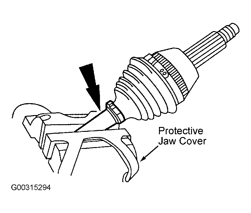
- Secure the halfshaft and Constant Velocity (CV) joint in a vise using protective jaw covers. See Fig 1
.
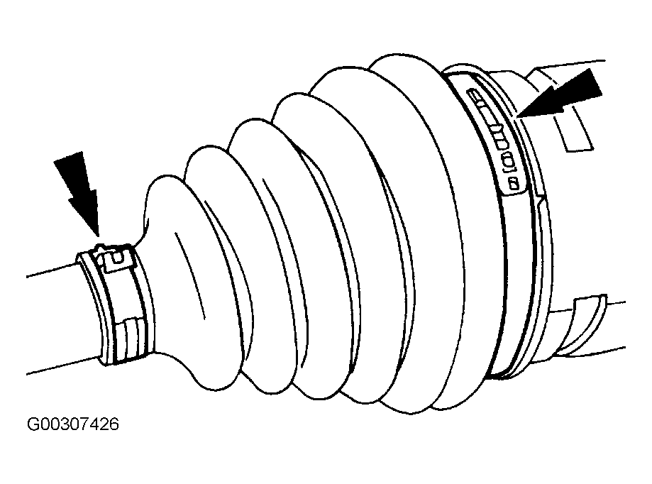
- Remove the inner halfshaft boot clamps. See Fig 2
.
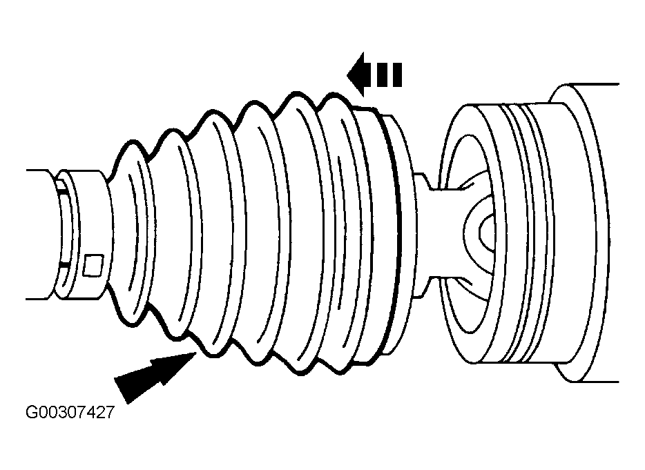
- Slide the inner halfshaft boot off the inner CV joint housing. See Fig 3
.
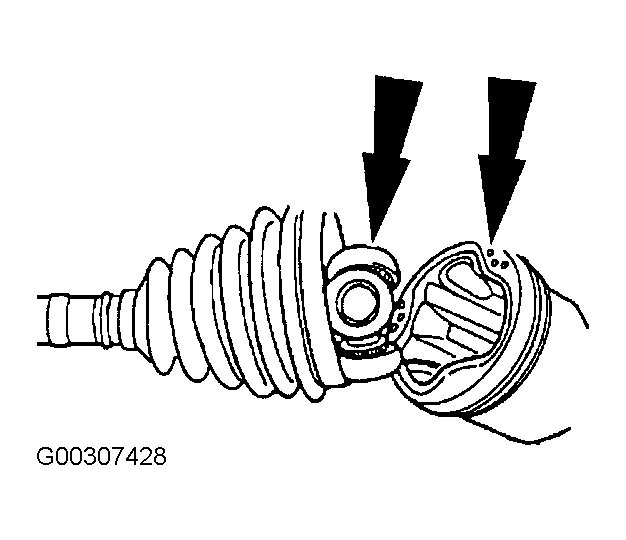
- Separate the tripod joint from the inner CV joint housing. See Fig 4
.
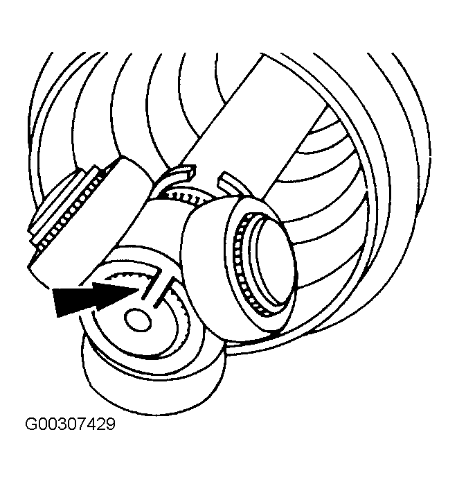
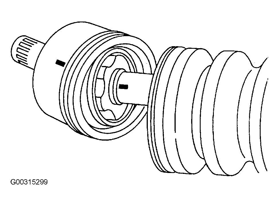
- If reinstalling the original tripod joint, mark the tripod joint and the halfshaft to make sure of correct installation. See Fig 5
.
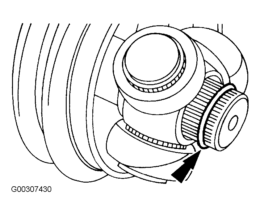
- Remove the snap ring. See Fig 6
.
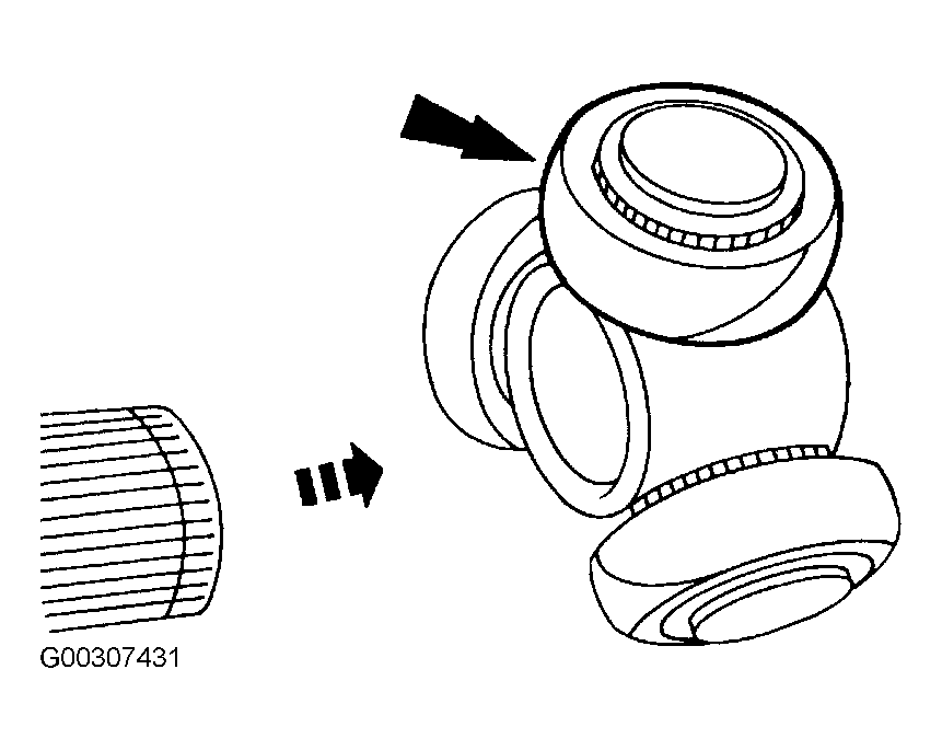
- Remove the tripod joint. See Fig 7
.
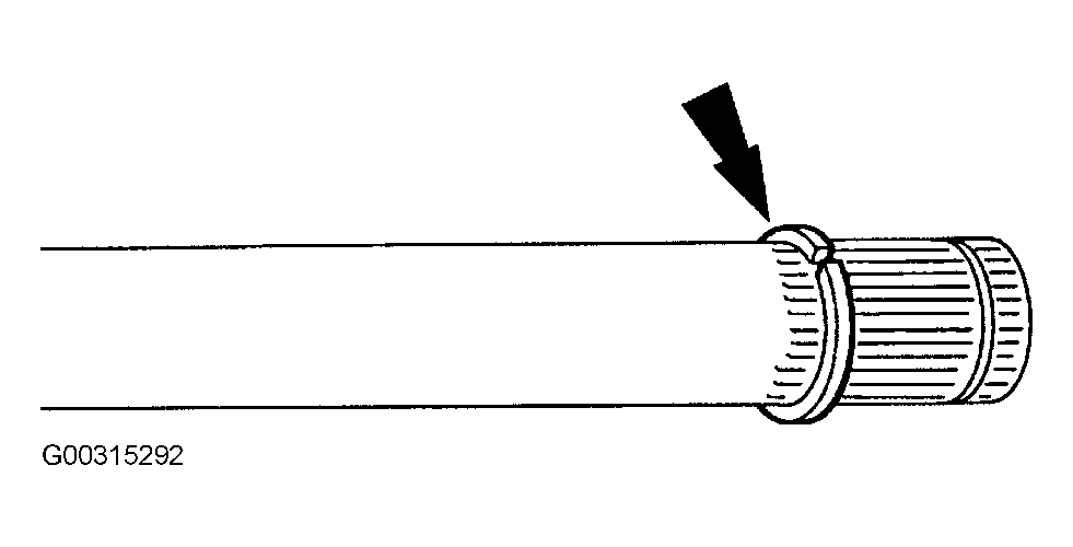
- Remove the snap ring. See Fig 8
.
- Remove the inner halfshaft boot from the halfshaft. See Fig 9
.
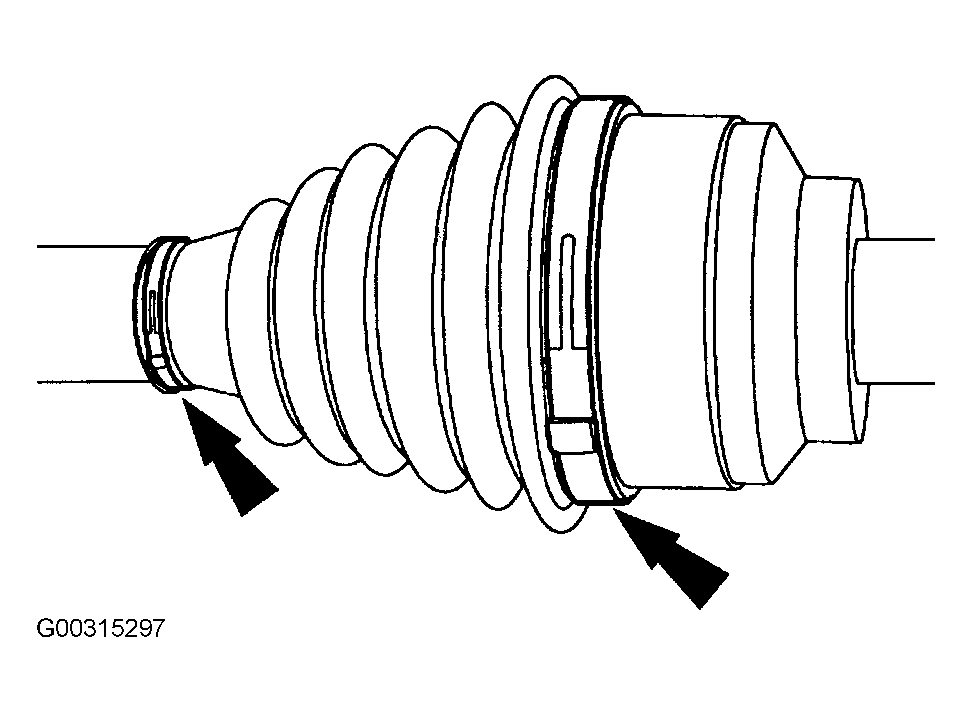
- Remove the two outer halfshaft boot clamps. See Fig 10
.
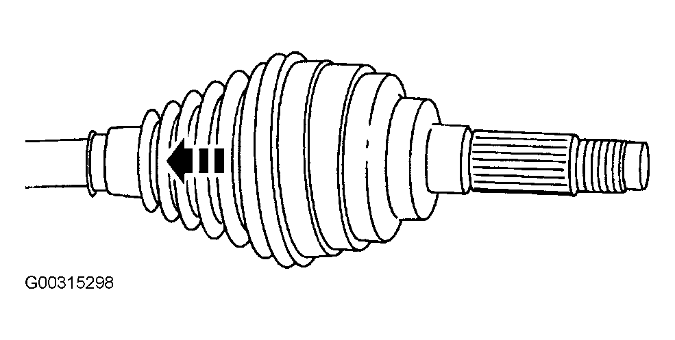
- Slide the outer halfshaft joint boot back out of the way exposing the outer CV joint. See Fig 11
.
- If reinstalling the original outer CV joint, mark the outer CV joint and halfshaft to make sure of correct installation. See Fig 12
.
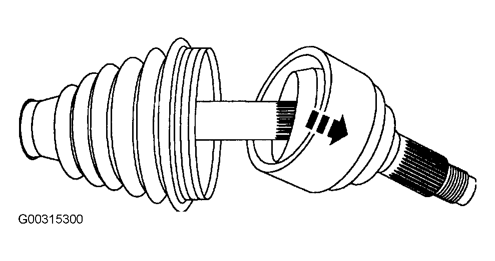
- Use a soft-face hammer to separate the outer CV joint by gently tapping it off the halfshaft. See Fig 13
.
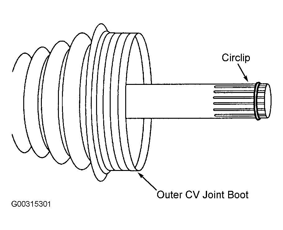
- Remove the halfshaft bearing retainer circlip and discard. See Fig 14
.
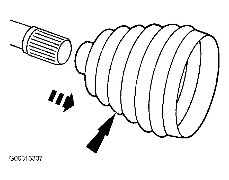
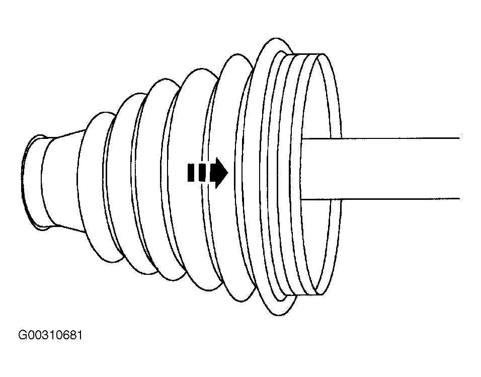
- Slide the outer halfshaft boot off of the halfshaft. See Fig 15
.
 Courtesy of FORD MOTOR CO.
 Courtesy of FORD MOTOR CO.
 Courtesy of FORD MOTOR CO.
 Courtesy of FORD MOTOR CO.
 Courtesy of FORD MOTOR CO.
 Courtesy of FORD MOTOR CO.
 Courtesy of FORD MOTOR CO.
 Courtesy of FORD MOTOR CO.
 Courtesy of FORD MOTOR CO.
 Courtesy of GENERAL MOTORS CORP.
 Courtesy of FORD MOTOR CO.
 Courtesy of FORD MOTOR CO.
 Courtesy of FORD MOTOR CO.
 Courtesy of FORD MOTOR CO.
 Courtesy of MAZDA MOTORS CORP.