Test M - High Beam Indicator Inoperative
- Turn ignition switch to LOCK position. Disconnect instrument cluster 12-pin harness connector C-215. Turn ignition switch to RUN position. Turn headlight switch to ON position. Set multifunction switch to HIGH beam position. Measure voltage at terminal No. 6 (Gray/White wire) at instrument cluster harness connector C-215. If voltage is greater than 10 volts, go to next step. If voltage is 10 volts or less and not equipped with Daytime Running Lights (DRL), repair open in Gray/White wire. If voltage is 10 volts or less and equipped with DRL, go to step 4).
- Turn ignition switch to LOCK position. Measure resistance between ground and terminal No. 7 (Black wire) at instrument cluster harness connector C-215. If resistance is 5 ohms or less, go to next step. If resistance is greater than 5 ohms, repair open In Black wire between instrument cluster and ground.
- Turn ignition switch to LOCK position. Remove instrument cluster. Check for continuity across high beam light bulb. If continuity exists, replace instrument cluster printed circuit. If continuity does not exist, replace bulb.
- Turn ignition switch to LOCK position. Disconnect DRL module harness connector. Turn ignition switch to RUN position. Turn headlight switch to ON position. Set multifunction switch to HIGH beam position. Measure voltage at terminal No. 8 (Light Green/Black wire) at DRL module harness connector. See Fig 1
. If voltage is greater than 10 volts, go to next step. If voltage is 10 volts or less, repair open in Light Green/Black wire.
- Turn ignition switch to LOCK position. Measure resistance in Gray/White wire between terminal No. 1 at DRL module harness connector and terminal No. 6 at instrument cluster harness connector C-215. See Figure
-Figure
and Fig 1
. If resistance is 5 ohms or less, replace DRL module. If resistance is greater than 5 ohms, repair open in Gray/White wire.
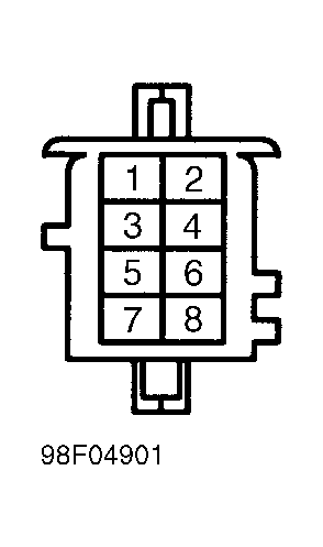 Courtesy of MAZDA MOTORS CORP.