Brake Pedal Height & Stoplight Switch: Protege
- Released pedal height is measured between brake pedal and stoplight switch mounting bracket. See Fig 1
. Disconnect stoplight switch electrical connector and remove switch. Measure clearance (length "L") between stoplight switch mounting bracket and brake pedal. See Fig 1
. Length should be .79-.90" (20-23 mm).
- If clearance is as specified, install stoplight switch. No adjustment is necessary. If clearance is not as specified, loosen lock nut "B" and rotate self-locking nut "A" counterclockwise until it does not contact brake pedal.
- Loosen push rod lock nut and rotate push rod until correct clearance between brake pedal and stoplight switch mounting bracket is obtained. Tighten push rod lock nut. Rotate self-locking nut "A" clockwise until clearance between brake pedal and end of self-locking nut "A" is .004-.039" (.1-1.0 mm). See Fig 1
. Tighten lock nut "B".
- Install NEW stoplight switch. Stoplight switch is automatically adjusted by pulling back on brake pedal until click noise is heard from switch. Reconnect stoplight switch electrical connector. Check stoplight operation. Adjust pedal free play. See BRAKE PEDAL FREE PLAY
.
- Applied pedal height is measured from angled portion of firewall (without carpet) to pedal pad center. Start engine. Depress brake pedal with 132 lbs. (60 kg) pressure. Distance should be 2.7" (70 mm). If distance is not as specified, check for air in system, rear brake adjustment (drum brakes) or worn shoes or pads. Repair as necessary.
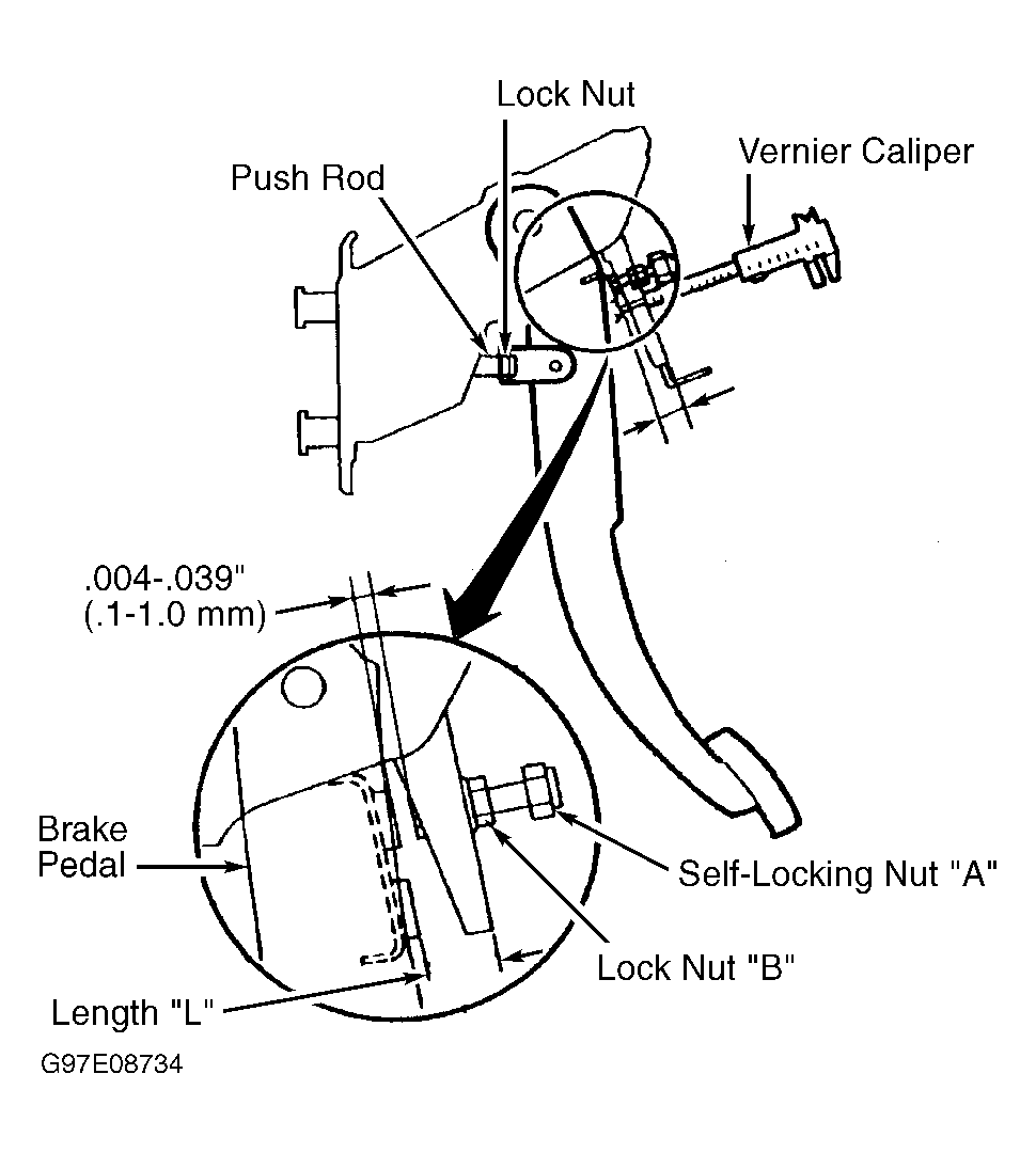 Courtesy of MAZDA MOTORS CORP.