Control Switch
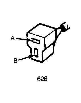 Courtesy of MAZDA MOTORS CORP.
- Detach control unit wire connector. Check for 12 volts at terminals "J" and "I". See Figure
. If 12 volts registers on the meter, control switch is satisfactory. If system performance is still unacceptable, continue to step 2) for wire harness test.
- With ignition on, disconnect the control unit wire harness connector. Attach voltmeter positive lead to terminal "M" on the harness side and negative lead to ground. See Figure
. Voltmeter should read 12 volts.
- Check for continuity in harness between control unit terminal "B" and control switch terminal "B". See Fig 1
. Ohmmeter should read continuity.
- Attach voltmeter positive lead to terminal "A" on the harness side of control switch connector and negative lead to ground. Voltmeter should again register 12 volts. If voltage is correct and control switch tests satisfactorily, an open or short in the wire harness is indicated.