Testing & Diagnosis: Actuator
- With ignition on, cycle the control switch between the "SPORT" and "NORMAL" positions. Use assistance to visually confirm that the control rod, viewed from the top of the actuator, is operating.
- If access to the rear actuator can not be obtained, confirmation can be made by listening for the sound of actuator operation.
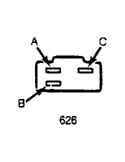 Courtesy of MAZDA MOTORS CORP.
- If wire harness requires testing, locate defective actuator(s) and disconnect sub-harness connector. On the harness side of the connector, attach voltmeter positive lead to terminal "A" and negative lead to terminal "C". As "SPORT" selection is pressed, 12 volts should appear on meter for approximately one second.
- Attach voltmeter positive lead to terminal "C" and negative lead to terminal "B". As "NORMAL" selection is pressed, 12 volts should appear on meter for approximately one second. If voltage test is satisfactory, a defective actuator is indicated. Actuator repair is not recommended. Replace unit as an assembly.
- If voltage readings are incorrect, disconnect control unit wire connector. Connect positive voltmeter lead to terminal "M" on the harness side of the connector. See Fig 2
. With ignition on, meter should read 12 volts. If not, a defective power circuit is indicated.
- Check for ground circuit continuity by attaching voltmeter positive lead to harness connector terminal "B" and negative lead to ground. If continuity does not exist, repair ground circuit wiring. If voltage and continuity readings are correct, control unit or switch is defective.
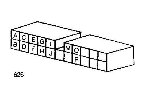 Courtesy of MAZDA MOTORS CORP.