Transmission Assembly
- If not done during transmission removal, drain fluid from transmission. Remove torque converter and place transmission in holding fixture. Separate governor tube from converter housing (if equipped). Remove housing.
- On all except L4N71B transmission, go to step 5
. On L4N71B transmissions, remove OD component assembly. Remove front clutch thrust washer and needle bearing and race. Draw out input shaft and intermediate shaft. Attach slide hammers (Datsun No. ST25850000) to pump and remove pump.
- Remove OD servo cover and loosen OD band servo piston stem. Remove OD pack (OD planetary gear and direct clutch assembly). Remove needle bearing and race and direct clutch thrust washer. Remove OD brake band and strut.
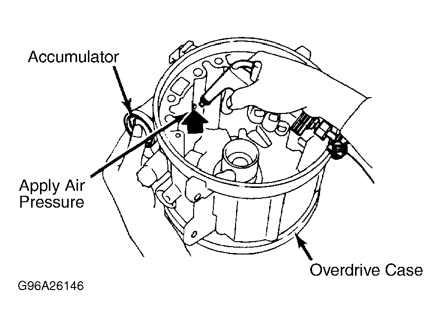
- Remove OD servo assembly by lightly tapping retainer. Remove accumulator snap ring and apply pressure to remove accumulator plug, piston and spring. Remove OD cancel solenoid and "O" ring. Remove drum support.
- On all models, remove downshift solenoid, vacuum diaphragm, diaphragm rod and "O" rings. Remove speedometer lock plate retaining bolt and remove speedometer pinion.
- Remove oil pan attaching bolts and oil pan. Remove valve body bolts. Remove valve body from transmission. Remove manual valve from valve body to prevent it from dropping out accidentally. Remove oil pan attaching bolts and oil pan. Remove valve body bolts. Remove valve body from transmission. See Fig 1
. Remove manual valve from valve body to prevent it from dropping out accidentally.
- On L4N71B transmissions, loosen second band servo piston stem lock nut and tighten piston stem if brake band is worn out. If it turns more than 2 turns, band is worn out. Back off band servo piston stem to release band.
- On L3N71B and 3N71B transmissions, loosen brake band adjusting screw lock nut and tighten screw just enough to prevent front clutch drum from dropping out when oil pump is removed.
- Remove input shaft from oil pump, then remove pump with slide hammers (Datsun No. ST25850000; Mazda No. 49 0378 39.0). Remove front clutch thrust washer and bearing race from front pump. Back off band servo piston stem to release band.
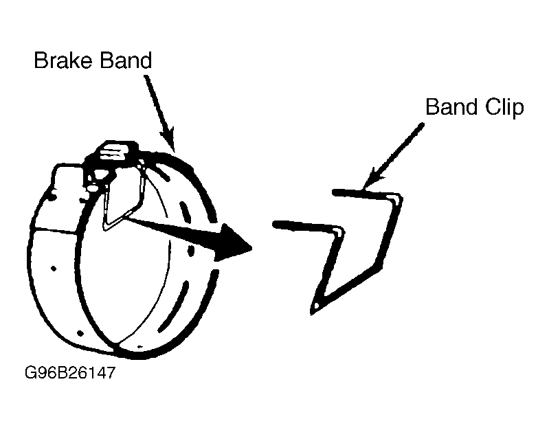
- On all transmissions, remove brake band strut. Before removing the brake band, secure with clip. See Fig 2
. Remove brake band, front clutch, rear clutch and front planetary gear set (if equipped) as an assembly. On 3N71B and L3N71B transmissions, remove front pump thrust bearing and rear clutch thrust washer.
- Remove rear clutch hub, front planetary carrier and connecting shell. Remove rear clutch thrust bearing, front planetary carrier thrust washer and thrust bearing.
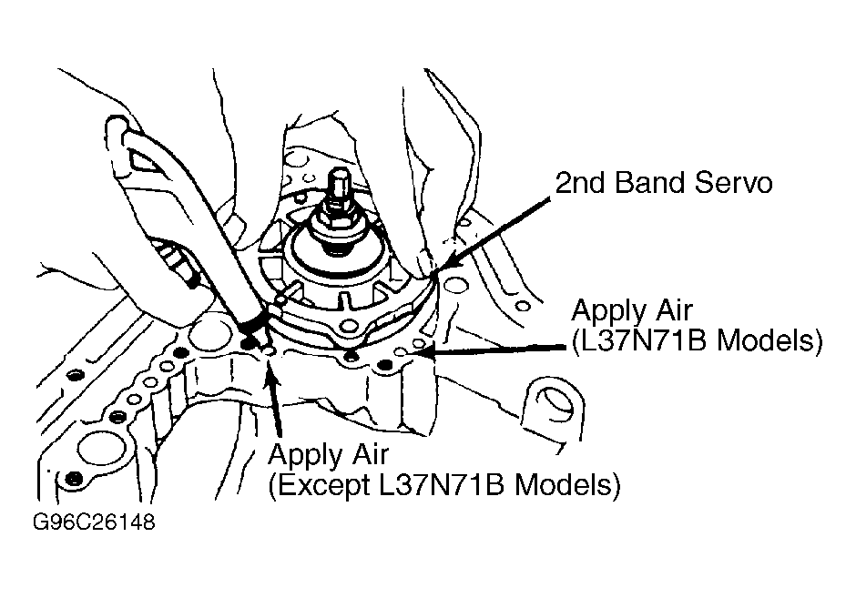
- On all transmissions, back out band servo attaching bolts about half-way. Carefully apply air pressure to loosen band servo. See Fig 3
. Remove band servo retaining bolts and pull band servo out. Remove rear planetary carrier snap ring. Remove rear planetary carrier. Remove output shaft snap ring.
- Remove rear connecting drum and internal annulus gear as an assembly. Pry off one end of low-reverse brake snap ring. Remove snap ring by gripping loose end of ring with pliers and turning it in direction away from gap in ring while pulling outward.
- Tilt extension housing upward and remove low-reverse brake clutch assembly. Remove extension housing being careful not to lose parking pawl, spring and retaining washer. Remove output shaft and governor as an assembly.
 Courtesy of NISSAN MOTOR CO., U.S.A.
 Courtesy of NISSAN MOTOR CO., U.S.A.
- Remove governor thrust washer and needle bearing. Remove one-way clutch inner race attaching bolts. Remove one-way clutch inner race, return thrust washer, low-reverse return spring and spring thrust ring.
- Apply air pressure to passage in transmission case to remove low-reverse brake piston. See Fig 4
. Remove snap rings from both ends of parking brake lever and remove lever.
 Courtesy of NISSAN MOTOR CO., U.S.A.
- Remove manual shaft lock nut, manual plate and parking rod. Remove inhibitor switch attaching bolts, inhibitor switch and manual shaft. On L4N71B transmissions, remove OD indicator switch and "O" ring.