Body Components (Model AUF 300, 301, 303 & 306)
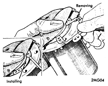
- (Guide plate type) Turn back the edge of the diaphragm and insert one end lobe of the armature guide plate into the recess between the armature and coil housing. Position all four lobes. Commencing in the center and finishing with the two end ones, press the lobes into the recess.
- Install the inlet and outlet connections with their sealing rings. Assemble outlet valve components in the outlet recess in the following order: A sealing washer, the valve (tongue side downward), then the valve cover.
- Install the inlet valve in the following order: A sealing washer, fuel filter (domeside downward), another sealing washer, the valve assembly (tongue side uppermost), and the valve cover.
- Making sure that both valve assemblies are properly positioned, place the clamp plate on top of the valve covers and tighten to the body with the two screws.
 Courtesy of NOT AVAILABLE
- Position the outlet valve disc in the outlet valve cage. Be sure the smooth face of the disc is against the valve seat. Hold the valve in place and install the lock ring in its groove. The valve must rattle when the cage is shaken.
- Drop the inlet valve disc, smooth face downward, on the valve seat in the pump. Insert the thin fibre washer, drop the valve cage in position and insert the medium fibre washer. Install the outlet union and tighten. Install the inlet union and filter.