Section 596 (Automatic Transmission - 6R80): Disassembly: Transmission
WARNING: This page is about a different car, the 2017 Lincoln Navigator and 2017 Ford Expedition. However, it is still accessible from the selected car via links, so may be relevant.
Special Tool (s)
 Courtesy of FORD MOTOR COMPANY Courtesy of FORD MOTOR COMPANY
|
Handle, Torque Converter 307-091 (T81P-7902-C) |
 Courtesy of FORD MOTOR COMPANY Courtesy of FORD MOTOR COMPANY
|
Holding Fixture, Transmission 307-003 (T57L-500-B) |
 Courtesy of FORD MOTOR COMPANY Courtesy of FORD MOTOR COMPANY
|
Installer, Front Wheel Hub Oil Seal 205-256 |
 Courtesy of FORD MOTOR COMPANY Courtesy of FORD MOTOR COMPANY
|
Remover, Axle Bearing 205-219 |
 Courtesy of FORD MOTOR COMPANY Courtesy of FORD MOTOR COMPANY
|
Remover, Input Shaft Oil Seal 308-375 |
 Courtesy of FORD MOTOR COMPANY Courtesy of FORD MOTOR COMPANY
|
Remover, Koastal Sleeve 307-717 |
 Courtesy of FORD MOTOR COMPANY Courtesy of FORD MOTOR COMPANY
|
Remover, Needle Bearing 307-562 (includes 307-562/1 and 307-562/2) |
 Courtesy of FORD MOTOR COMPANY Courtesy of FORD MOTOR COMPANY
|
Remover, Transmission Fluid Pump 307-553 |
 Courtesy of FORD MOTOR COMPANY Courtesy of FORD MOTOR COMPANY
|
Retaining Ring Pliers 307-343 (T95P-77001-AHR) |
 Courtesy of FORD MOTOR COMPANY Courtesy of FORD MOTOR COMPANY
|
Slide Hammer 100-001 (T50T-100-A) |
All vehicles
- 1.
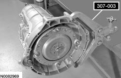
Install the Transmission Holding Fixture on the torque converter housing and install the transmission on a bench.
 Courtesy of FORD MOTOR COMPANY Courtesy of FORD MOTOR COMPANY
|
- 2.
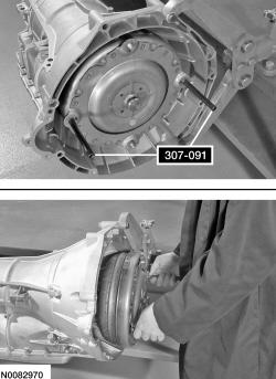
Using the Torque Converter Handle, remove the torque converter.
 Courtesy of FORD MOTOR COMPANY Courtesy of FORD MOTOR COMPANY
|
- 3.
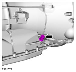
Remove the transmission fluid fill plug.
 Courtesy of FORD MOTOR COMPANY Courtesy of FORD MOTOR COMPANY
|
- 4.
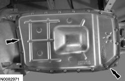
Remove the transmission fluid pan bolts and the transmission fluid pan.
 Courtesy of FORD MOTOR COMPANY Courtesy of FORD MOTOR COMPANY
|
- 5.
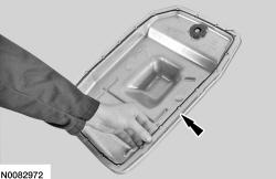
Remove the transmission fluid pan gasket.
 Courtesy of FORD MOTOR COMPANY Courtesy of FORD MOTOR COMPANY
|
- 6.
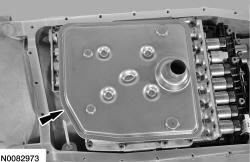
Remove and discard the transmission fluid filter.
 Courtesy of FORD MOTOR COMPANY Courtesy of FORD MOTOR COMPANY
|
- 7.
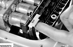
Press the release tab and lift up on the bulkhead connector sleeve retainer to release the bulkhead connector sleeve shell.
 Courtesy of FORD MOTOR COMPANY Courtesy of FORD MOTOR COMPANY
|
- 8.
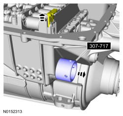
With the transmission bulkhead connector sleeve retainer released, use the Koastal Sleeve Remover to pull the outer shell of the bulkhead connector sleeve out of the transmission.
 Courtesy of FORD MOTOR COMPANY Courtesy of FORD MOTOR COMPANY
|
- 9.
Inspect the bulkhead connector sleeve seals.
- If necessary, replace the seals.
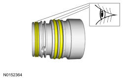 Courtesy of FORD MOTOR COMPANY Courtesy of FORD MOTOR COMPANY
|
- 10.
Remove the 11 bolts from the main control assembly.
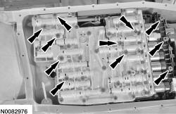 Courtesy of FORD MOTOR COMPANY Courtesy of FORD MOTOR COMPANY
|
- 11.
Remove the main control assembly.
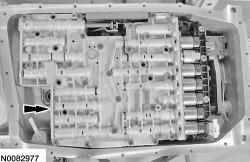 Courtesy of FORD MOTOR COMPANY Courtesy of FORD MOTOR COMPANY
|
- 12.
Remove the front pump adapter seal and the transmission fluid filter seal. Inspect for cracks or damage.
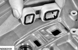 Courtesy of FORD MOTOR COMPANY Courtesy of FORD MOTOR COMPANY
|
- 13.
NOTE:
Note the color, size and location while removing for correct assembly.
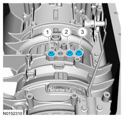
Remove and discard the 3 center support feed tube seals.
- 1.
Center support feed tube seal (7G199 Black)
- 2.
Center support feed tube seal (7G087 Green or Orange)
- 3.
Center support feed tube seal (7G084 Blue)
 Courtesy of FORD MOTOR COMPANY Courtesy of FORD MOTOR COMPANY
|
- 14.
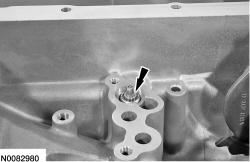
Remove the thermal bypass valve from the case.
 Courtesy of FORD MOTOR COMPANY Courtesy of FORD MOTOR COMPANY
|
- 15.
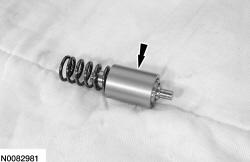
Inspect the thermal bypass valve for damage and install a new valve if damaged.
 Courtesy of FORD MOTOR COMPANY Courtesy of FORD MOTOR COMPANY
|
- 16.
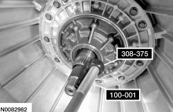
Using the Input Shaft Oil Seal Remover and Slide Hammer, remove and discard the front pump seal.
 Courtesy of FORD MOTOR COMPANY Courtesy of FORD MOTOR COMPANY
|
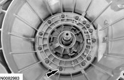
- 17.
Remove and discard the 13 front pump-to-case bolts and washers.
 Courtesy of FORD MOTOR COMPANY Courtesy of FORD MOTOR COMPANY
|
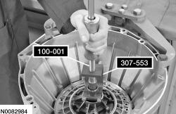
- 18.
Using the Transmission Fluid Pump Remover and Slide Hammer, remove the front pump support.
 Courtesy of FORD MOTOR COMPANY Courtesy of FORD MOTOR COMPANY
|
- 19.
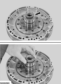
NOTE:
The selective shim may come out while removing the front pump.
Inspect the back of the front pump for the selective shim and remove If necessary.
 Courtesy of FORD MOTOR COMPANY Courtesy of FORD MOTOR COMPANY
|
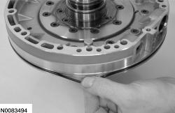
- 20.
Remove and discard the front pump O-ring seal.
 Courtesy of FORD MOTOR COMPANY Courtesy of FORD MOTOR COMPANY
|
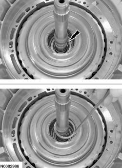
- 21.
If the selective shim is not on the pump, using a magnet, remove it from the forward (A)/overdrive (E) clutch assembly.
 Courtesy of FORD MOTOR COMPANY Courtesy of FORD MOTOR COMPANY
|
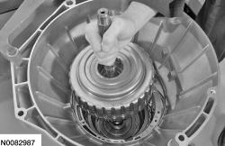
- 22.
Remove the forward (A)/overdrive (E) clutch assembly.
 Courtesy of FORD MOTOR COMPANY Courtesy of FORD MOTOR COMPANY
|
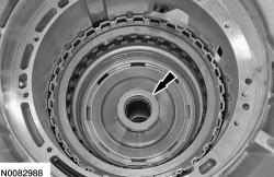
- 23.
Remove the caged T5 roller bearing from the direct (B) clutch assembly.
 Courtesy of FORD MOTOR COMPANY Courtesy of FORD MOTOR COMPANY
|
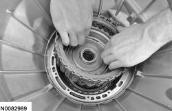
- 24.
Remove the direct (B) clutch assembly.
 Courtesy of FORD MOTOR COMPANY Courtesy of FORD MOTOR COMPANY
|
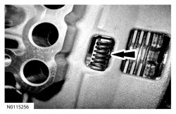
- 25.
Remove the bias spring.
 Courtesy of FORD MOTOR COMPANY Courtesy of FORD MOTOR COMPANY
|
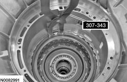
- 26.
Using the Retaining Ring Pliers, remove the center support snap ring.
 Courtesy of FORD MOTOR COMPANY Courtesy of FORD MOTOR COMPANY
|
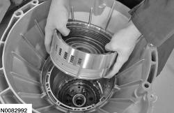
- 27.
Remove the center support and T6 bearing.
 Courtesy of FORD MOTOR COMPANY Courtesy of FORD MOTOR COMPANY
|
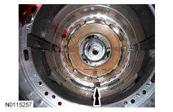
- 28.
NOTE:
When removing the OWC, note the position for assembly.
Remove the OWC.
 Courtesy of FORD MOTOR COMPANY Courtesy of FORD MOTOR COMPANY
|
- 29.
NOTE:
The selective shim might stick to the T7 thrust bearing during removal of the center support.
Remove the selective shim and the T7 thrust bearing.
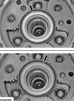 Courtesy of FORD MOTOR COMPANY Courtesy of FORD MOTOR COMPANY
|
- 30.
NOTE:
The selective shim might stick to the back of the center support assembly during removal.
Remove the selective shim from the center support assembly.
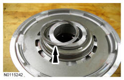 Courtesy of FORD MOTOR COMPANY Courtesy of FORD MOTOR COMPANY
|
- 31.
NOTE:
Some of the clutch plates may stay in the case when removing the planetary carrier and the low/reverse clutch pack. Remove any clutch plates from the transmission that were not removed with the carrier and keep the clutch plates together.
Remove the planetary carrier and the low/reverse clutch pack as an assembly.
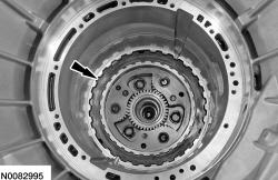 Courtesy of FORD MOTOR COMPANY Courtesy of FORD MOTOR COMPANY
|
- 32.
Remove the No. 2 sun gear and race.
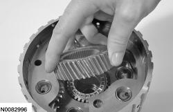 Courtesy of FORD MOTOR COMPANY Courtesy of FORD MOTOR COMPANY
|
- 33.
NOTE:
Remove the bearings with the sun gear.
NOTE:
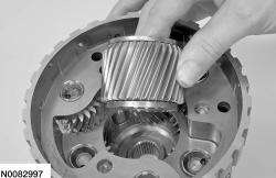
When removing the sun gear, note that the tapered edge is facing up toward the torque converter housing.
Remove the No. 3 sun gear from the planetary assembly.
 Courtesy of FORD MOTOR COMPANY Courtesy of FORD MOTOR COMPANY
|
- 34.
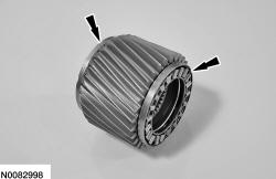
Remove the top T8 and the bottom T9 roller bearings from the sun gear.
 Courtesy of FORD MOTOR COMPANY Courtesy of FORD MOTOR COMPANY
|
- 35.
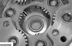
Remove the T9 roller bearing race from the bottom of the carrier.
 Courtesy of FORD MOTOR COMPANY Courtesy of FORD MOTOR COMPANY
|
- 36.
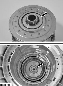
Remove the T10 thrust bearing from either the rear planetary carrier or the output shaft assembly.
 Courtesy of FORD MOTOR COMPANY Courtesy of FORD MOTOR COMPANY
|
Rear Wheel Drive (RWD) vehicles
- 37.
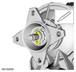
Remove the stakes from the output shaft flange retaining nut.
 Courtesy of FORD MOTOR COMPANY Courtesy of FORD MOTOR COMPANY
|
- 38.
NOTE:
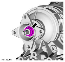
The output shaft flange retaining nut has been staked to prevent it from coming loose. Prior to removing the nut, remove the stake to prevent damage to the output shaft.
Place the manual control lever in the PARK position and remove and discard the output shaft flange retaining nut.
 Courtesy of FORD MOTOR COMPANY Courtesy of FORD MOTOR COMPANY
|
- 39.
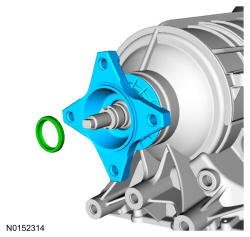
Remove the output shaft flange and the output shaft flange seal.
 Courtesy of FORD MOTOR COMPANY Courtesy of FORD MOTOR COMPANY
|
- 40.
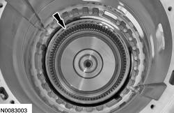
Remove the planetary carrier hub, output shaft assembly and T11 bearing.
 Courtesy of FORD MOTOR COMPANY Courtesy of FORD MOTOR COMPANY
|
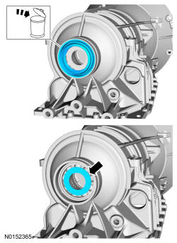
- 41.
Remove the output shaft seal and the slip plane washer.
- Discard the output shaft seal.
 Courtesy of FORD MOTOR COMPANY Courtesy of FORD MOTOR COMPANY
|
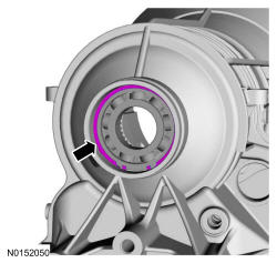
- 42.
Remove the output shaft ball bearing snap ring.
 Courtesy of FORD MOTOR COMPANY Courtesy of FORD MOTOR COMPANY
|
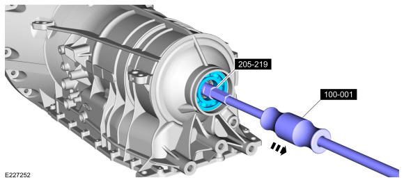
- 43.
Using the Slide Hammer and Axle Bearing Remover, remove the output shaft ball bearing.
 Courtesy of FORD MOTOR COMPANY Courtesy of FORD MOTOR COMPANY
|
Four-Wheel Drive (4WD) vehicles
- 44.
Remove the planet carrier hub, output shaft assembly and T11 bearing.
Courtesy of FORD MOTOR COMPANY
|
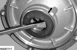
- 45.
Remove and discard the output shaft seal.
 Courtesy of FORD MOTOR COMPANY Courtesy of FORD MOTOR COMPANY
|
All vehicles
- 46.
NOTE:
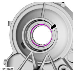
RWD case shown, 4WD case similar.
Remove the snap ring.
 Courtesy of FORD MOTOR COMPANY Courtesy of FORD MOTOR COMPANY
|
- 47.
NOTE:
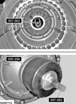
Use care when installing the Needle Bearing Remover. Look inside the transmission case to make sure that the Needle Bearing Remover contacts the bearing only and not the lip of the case, or damage to the case will occur.
Using the Needle Bearing Remover and the Front Wheel Hub Oil Seal Installer, remove the bearing assembly.
 Courtesy of FORD MOTOR COMPANY Courtesy of FORD MOTOR COMPANY
|
- 48.
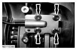
Remove and discard the 4 park rod actuating plate bolts and the park rod actuating plate.
 Courtesy of FORD MOTOR COMPANY Courtesy of FORD MOTOR COMPANY
|
- 49.
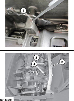
Remove the manual control lever detent plate and park pawl actuator rod from the transmission case.
- 1.
Remove and discard the roll pin.
- 2.
Slide the manual control lever shaft out of the case.
- 3.
Hold the manual control lever spacer to keep it from falling into the case.
- 4.
Remove the manual valve detent lever and park pawl actuator rod as an assembly.
 Courtesy of FORD MOTOR COMPANY Courtesy of FORD MOTOR COMPANY
|
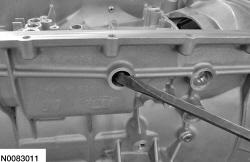
- 50.
Remove and discard the manual control lever shaft seal.
 Courtesy of FORD MOTOR COMPANY Courtesy of FORD MOTOR COMPANY
|
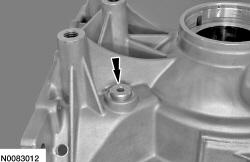
- 51.
Remove the bolt from the back of the case to gain access to the park pawl pin.
 Courtesy of FORD MOTOR COMPANY Courtesy of FORD MOTOR COMPANY
|
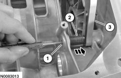
- 52.
From the inside of the case, push the park pawl pin out toward the back side of the case while holding the park pawl return spring and the park pawl. Remove the park pawl pin then remove the park pawl and spring.
- 1.
Park pawl pin
- 2.
Park pawl return spring
- 3.
Park pawl
 Courtesy of FORD MOTOR COMPANY Courtesy of FORD MOTOR COMPANY
|
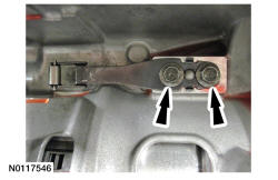
- 53.
Remove and discard the 2 bolts and the park detent spring.
 Courtesy of FORD MOTOR COMPANY Courtesy of FORD MOTOR COMPANY
|