Pinpoint Test A: All DIMMABLE Illumination Does Not Dim
- A1 CHECK THE RECORDED RESULTS FROM THE SCCM ON-DEMAND SELF-TEST
- Ignition OFF.
- Using a scan tool, perform the SCCM self-test.
- Is DTC B1124:09 present?
- Yes
: GO to A2.
- No
: GO to A4.
- A2 CHECK THE INSTRUMENT PANEL DIMMER SWITCH
- Disconnect: Instrument Panel Dimmer Switch C2065.
- Ignition ON.
- Using a scan tool, clear the DTCs and perform the SCCM self-test.
- Is DTC B1124:09 still present?
- A3 CHECK THE INSTRUMENT PANEL DIMMER SWITCH INPUT CIRCUITS FOR A SHORT TO GROUND
- Ignition OFF.
- Disconnect: SCCM C2414A.
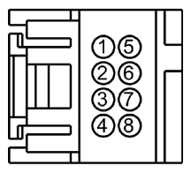
- Measure the resistance
between:
| Positive Lead |
Negative Lead |
| Pin |
Circuit |
Pin |
Circuit |
| C2065-2 |
VLN36 (GY/OG) |
- |
Ground |
| C2065-3 |
CLN56 (BN/VT) |
- |
Ground |
| C2065-7 |
CLN55 (YE/VT) |
- |
Ground |
 Courtesy of FORD MOTOR CO.
- Are the resistances greater than 10, 000 ohms?
- Yes
: GO to A9.
- No
: REPAIR the affected circuit.
- A4 CHECK THE INSTRUMENT PANEL DIMMER SWITCH
- Disconnect: Instrument Panel Dimmer Switch C2065.
- Carry out the instrument panel dimmer switch component test. Refer to the
OEM COMPONENT TESTING article.
- Is the instrument panel dimmer switch OK?
- A5 CHECK THE INSTRUMENT PANEL DIMMER SWITCH UP AND DOWN INPUT CIRCUITS FOR VOLTAGE
- Ignition ON.
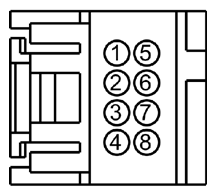
- Measure the voltage
between:
| Positive Lead |
Negative Lead |
| Pin |
Circuit |
Pin |
Circuit |
| C2065-3 |
CLN56 (BN/VT) |
- |
Ground |
| C2065-7 |
CLN55 (YE/VT) |
- |
Ground |
 Courtesy of FORD MOTOR CO.
- Are the voltages approximately 5 volts?
- Yes
: GO to A7.
- No
: GO to A6.
- A6 CHECK THE INSTRUMENT PANEL DIMMER SWITCH UP AND DOWN INPUT CIRCUITS FOR AN OPEN
- Ignition OFF.
- Disconnect: SCCM C2414A.
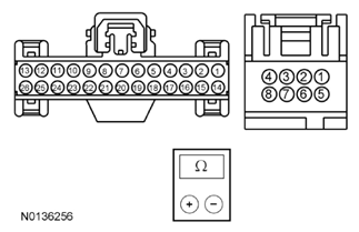
- Measure the resistance
between:
| Positive Lead |
Negative Lead |
| Pin |
Circuit |
Pin |
Circuit |
| C2414A-17 |
CLN56 (BN/VT) |
C2065-3 |
CLN56 (BN/VT) |
| C2414A-18 |
CLN55 (YE/VT) |
C2065-7 |
CLN55 (YE/VT) |
 Courtesy of FORD MOTOR CO.
- Are the resistances less than 3 ohms?
- Yes
: GO to A9.
- No
: REPAIR the affected circuit.
- A7 CHECK THE INSTRUMENT PANEL DIMMER SWITCH INPUT AND RETURN CIRCUITS FOR A SHORT TO VOLTAGE
- Ignition OFF.
- Disconnect: SCCM C2414A.
- Ignition ON.
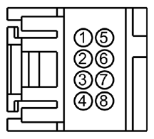
- Measure the voltage
between:
| Positive Lead |
Negative Lead |
| Pin |
Circuit |
Pin |
Circuit |
| C2065-2 |
VLN36 (GY/OG) |
- |
Ground |
| C2065-3 |
CLN56 (BN/VT) |
- |
Ground |
| C2065-4 |
RLN29 (WH/OG) |
- |
Ground |
| C2065-7 |
CLN55 (YE/VT) |
- |
Ground |
 Courtesy of FORD MOTOR CO.
- Is any voltage present?
- Yes
: REPAIR the affected circuit.
- No
: GO to A8.
- A8 CHECK THE INSTRUMENT PANEL DIMMER SWITCH RETURN CIRCUIT FOR AN OPEN
- Ignition OFF.
- Measure the resistance
between:
| Positive Lead |
Negative Lead |
| Pin |
Circuit |
Pin |
Circuit |
| C2414A-15 |
RLN29 (WH/OG) |
C2065-4 |
RLN29 (WH/OG) |
Courtesy of FORD MOTOR CO.
- Is the resistance less than 3 ohms?
- Yes
: GO to A9.
- No
: REPAIR the circuit.
- A9 CHECK THE INSTRUMENT PANEL DIMMER SWITCH INPUT AND RETURN CIRCUITS FOR A SHORT TOGETHER
- Measure the resistance
between:
| Positive Lead |
Negative Lead |
| Pin |
Circuit |
Pin |
Circuit |
| C2065-2 |
VLN36 (GY/OG) |
C2065-3 |
CLN56 (BN/VT) |
| C2065-2 |
VLN36 (GY/OG) |
C2065-4 |
RLN29 (WH/OG) |
| C2065-2 |
VLN36 (GY/OG) |
C2065-7 |
CLN55 (YE/VT) |
| C2065-3 |
CLN56 (BN/VT) |
C2065-4 |
RLN29 (WH/OG) |
| C2065-3 |
CLN56 (BN/VT) |
C2065-7 |
CLN55 (YE/VT) |
| C2065-4 |
RLN29 (WH/OG) |
C2065-7 |
CLN55 (YE/VT) |
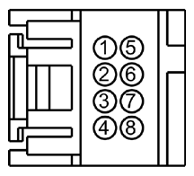 Courtesy of FORD MOTOR CO.
- Are the resistances greater than 10, 000 ohms?
- Yes
: GO to A10.
- No
: REPAIR the affected circuits.
- A10 CHECK FOR CORRECT SCCM OPERATION
- Disconnect and inspect all the SCCM connectors.
- Repair:
- corrosion (install new connector or terminals - clean module pins)
- damaged or bent pins - install new terminals/pins
- pushed-out pins - install new pins as necessary
- Reconnect the SCCM connectors. Make sure they seat and latch correctly.
- Operate the system and determine if the concern is still present.
- Is the concern still present?
- Yes
: CHECK On-Line Automotive Service Information System (OASIS) for any applicable TSBs. If a TSB exists for this concern, DISCONTINUE this test and FOLLOW TSB instructions. If no TSBs address this concern, INSTALL a new SCCM. REFER to
STEERING COLUMN SWITCHES
.
- No
: The system is operating correctly at this time. The concern may have been caused by module connections. ADDRESS the root cause of any connector or pin issues.