Pinpoint Test D: The Low Beam(s) Are Always On
Headlamps
Pinpoint Test D: The Low Beam(s) Are Always On
Refer to Wiring Diagram Set 85, Headlamps/Autolamps for schematic and connector information Electrical Diagrams.
Normal Operation
The SJB (Smart Junction Box) sends reference signals to the headlamp switch through the headlamp switch input circuits (off, parking lamps, headlamps). At any given time, the headlamp switch routes one of the input circuits to ground. If the SJB (Smart Junction Box) detects multiple inputs active or no inputs active for 5 seconds, the SJB (Smart Junction Box) turns the parking lamps and headlamps on.
Expedition
When the SJB (Smart Junction Box) detects the headlamp switch in the HEADLAMPS ON position, the SJB (Smart Junction Box) provides voltage through the LH headlamp voltage supply circuit to the LH low beam headlamp and the RH headlamp voltage supply circuit to the RH low beam headlamp.
Navigator
When the SJB (Smart Junction Box) detects the headlamp switch in the HEADLAMPS ON position, the SJB (Smart Junction Box) provides voltage to the LH and RH High Intensity Discharge (HID) relay coils. When the relays are energized, voltage is routed to the LH and RH headlamps.
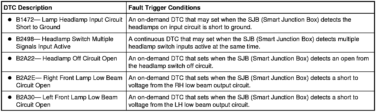
This pinpoint test is intended to diagnose the following:
- Wiring, terminals or connectors
- HID (High Intensity Discharge) relay
- Headlamp switch
- SJB (Smart Junction Box)
PINPOINT TEST D : THE LOW BEAM(S) ARE ALWAYS ON
NOTICE: Use the correct probe adapter(s) when making measurements. Failure to use the correct probe adapter(s) may damage the connector.
NOTE: Failure to disconnect the battery when instructed will result in false resistance readings.
D1 CHECK FOR AUTOLAMP DTCs
- Review the DTCs retrieved from the SJB self-test.
Is DTC B1696, B1791, B1793 or B2008 present?
Yes
REFER to Autolamps. Testing and Inspection
No
GO to D2.
D2 CHECK THE SJB (Smart Junction Box) AUTOLAMP ON REQUEST PID
- Ignition ON.
- Enter the following diagnostic mode on the scan tool: SJB (Smart Junction Box) Data Logger.
- While placing the headlamp switch in the AUTOLAMPS ON and then OFF position, monitor the SJB (Smart Junction Box) headlamp switch PID (HDLMP_AUT_CKT).
Does the PID indicate ON with the headlamp switch in the AUTOLAMPS ON position and OFF when the headlamp switch is in the OFF position?
Yes
GO to D3.
No
GO to Pinpoint Test H. Pinpoint Test H: The Autolamps Are On Continuously
D3 CHECK THE SJB (Smart Junction Box) HEADLAMP SWITCH PIDs
NOTE: Make sure the headlamp switch is lined up in the correct position when monitoring the PIDs.
NOTE: Only one PID should indicate ON at each headlamp switch position.
- Enter the following diagnostic mode on the scan tool: SJB (Smart Junction Box) Data Logger.
- While moving the headlamp switch through all positions, monitor the SJB (Smart Junction Box) headlamp switch input PIDs (HDLMP_OFF_CKT, HDLMP_PRK_CKT, HDLMP_ON_CKT).
Do the headlamp switch positions agree with the PIDs (with only one PID indicating ON in each position)?
Yes
GO to D8.
No
GO to D4.
D4 CHECK FOR VOLTAGE TO THE HEADLAMP SWITCH INPUT CIRCUIT
- Ignition OFF.
- Disconnect: Headlamp Switch C205.
- Measure the voltage between the headlamp switch, harness side and ground as follows:
Headlamp Switch Connector-Pin Circuit C205-9 CLF23 (WH/VT) C205-5 CLS05 (BU/GY) C205-10 CLF24 (YE/BU)
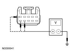
Is the voltage greater than 10 volts?
Yes
GO to D5.
No
GO to D6.
D5 CHECK FOR VOLTAGE TO THE HEADLAMP SWITCH USING THE CONNECTOR GROUND
- Measure the voltage between the headlamp switch C205-10, circuit CLF24 (YE/BU), harness side and the headlamp switch C205-7, circuit GD138 (BK/WH), harness side.
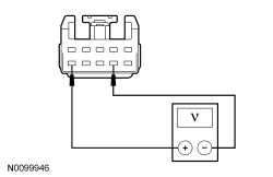
Is the voltage greater than 10 volts?
Yes
INSTALL a new headlamp switch. REFER to Headlamp Switch . CLEAR the DTCs. REPEAT the self-test.
No
REPAIR circuit GD138 (BK/WH) for an open. CLEAR the DTCs. REPEAT the self-test.
D6 CHECK THE HEADLAMP SWITCH INPUT CIRCUITS FOR A SHORT TO GROUND
- Disconnect: SJB (Smart Junction Box) C2280B.
- Measure the resistance between the headlamp switch, harness side and ground as follows:
Headlamp Switch Connector-Pin Circuit C205-9 CLF23 (WH/VT) C205-5 CLS05 (BU/GY) C205-10 CLF24 (YE/BU)
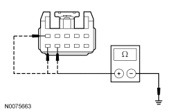
Are the resistances greater than 10,000 ohms?
Yes
GO to D7.
No
REPAIR the circuit in question. CLEAR the DTCs. REPEAT the self-test.
D7 CHECK THE HEADLAMP SWITCH INPUT CIRCUITS FOR AN OPEN
- Measure the resistance between the headlamp switch, harness side and the SJB (Smart Junction Box), harness side as follows:
Headlamp Switch Connector-Pin SJB (Smart Junction Box) Connector-Pin Circuit C205-9 C2280B-47 CLF23 (WH/VT) C205-5 C2280B-31 CLS05 (BU/GY) C205-10 C2280B-30 CLF24 (YE/BU)
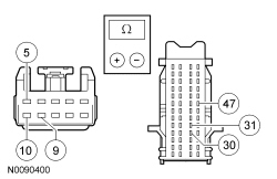
Are the resistances less than 5 ohms?
Yes
GO to D11.
No
REPAIR the circuit in question. CLEAR the DTCs. REPEAT the self-test.
D8 CHECK THE SJB (Smart Junction Box) OUTPUT
- Disconnect: SJB (Smart Junction Box) C2280E.
Does the LH or RH headlamp continue to illuminate?
Yes
For Expedition, REPAIR circuit CLF04 (BN/BU) (LH headlamp) or circuit CLF05 (BU/GN) (RH headlamp) for a short to voltage. CLEAR the DTCs. REPEAT the self-test.
For Navigator, GO to D9.
No
GO to D11.
D9 CHECK THE HID (High Intensity Discharge) RELAY OUTPUT CIRCUIT FOR A SHORT TO VOLTAGE
- Disconnect: Suspect HID (High Intensity Discharge) Relay.
Does the LH or RH headlamp continue to illuminate?
Yes
REPAIR circuit CLF30 (VT/BN) (LH headlamp) or circuit CLF31 (YE/GY) (RH headlamp) for a short to voltage. CLEAR the DTCs. REPEAT the self-test.
No
GO to D10.
D10 CHECK THE HID (High Intensity Discharge) RELAY
- Substitute a known good relay.
Does the headlamp in question continue to illuminate?
Yes
INSTALL a new HID (High Intensity Discharge) relay. CLEAR the DTCs. REPEAT the self-test.
No
REPAIR circuit CLF04 (BN/BU) (LH headlamp) or circuit CLF05 (BU/GN) (RH headlamp) for a short to voltage. CLEAR the DTCs. REPEAT the self-test.
D11 CHECK FOR CORRECT SJB (Smart Junction Box) OPERATION
- Ignition OFF.
- Disconnect all the SJB (Smart Junction Box) connectors.
- Check for:
- corrosion
- damaged pins
- pushed-out pins
- Connect all the SJB (Smart Junction Box) connectors and make sure they seat correctly.
- Operate the system and verify the concern is still present.
Is the concern still present?
Yes
INSTALL a new SJB (Smart Junction Box). TEST the system for normal operation.
No
The system is operating correctly at this time. The concern may have been caused by a loose or corroded connector. CLEAR the DTCs. REPEAT the self-test.