Pinpoint Test A: The Instrument Cluster (IC) Is Inoperative
Instrumentation, Message Center and Warning Chimes
Pinpoint Test A: The Instrument Cluster (IC) Is Inoperative
Refer to Wiring Diagram Set 60, Instrument Cluster for schematic and connector information Electrical Diagrams.
Normal Operation
The Instrument Cluster (IC) receives both the RUN/START and keep alive voltage inputs from the Smart Junction Box (SJB). The IC (Instrument Cluster) is grounded through a single hardwired ground.
This pinpoint test is intended to diagnose the following:
- Fuse(s)
- Wiring, terminals or connectors
- IC (Instrument Cluster)
PINPOINT TEST A : THE IC (Instrument Cluster) IS INOPERATIVE
NOTICE: Use the correct probe adapter(s) when making measurements. Failure to use the correct probe adapter(s) may damage the connector.
NOTE: Failure to disconnect the battery when instructed will result in false resistance readings.
A1 CARRY OUT THE NETWORK TEST
NOTE: If the Medium Speed Controller Area Network (MS-CAN) is damaged or disconnected, the IC (Instrument Cluster) could appear to be inoperative, the vehicle may not start while the theft indicator appears to be functioning correctly.
- Ignition ON.
- Enter the following diagnostic mode on the scan tool: Network Test.
- Carry out the vehicle network test.
Do all modules communicate on the MS-CAN (Medium Speed Controller Area Network) network?
Yes
GO to A2.
No
REFER to Information Bus to diagnose the communication network.
A2 CHECK THE HOT AT ALL TIMES VOLTAGE SUPPLY CIRCUIT FOR VOLTAGE
- Ignition OFF.
- Disconnect: IC (Instrument Cluster) C220.
- Measure the voltage between the IC (Instrument Cluster) C220-1, circuit SBP26 (YE/RD), harness side and ground.
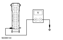
Is the voltage greater than 10 volts?
Yes
GO to A3.
No
VERIFY the SJB (Smart Junction Box) fuse 26 (10A) is OK. If OK, REPAIR circuit SBP26 (YE/RD) for an open. TEST the system for normal operation. If not OK, REFER to the Wiring Diagrams to identify the possible causes of the circuit short Electrical Diagrams.
A3 CHECK THE IC (Instrument Cluster) RUN/START VOLTAGE SUPPLY
- Ignition ON.
- Measure the voltage between the IC (Instrument Cluster) C220-14, circuit CBP29 (WH/VT), harness side and ground.
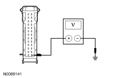
Is the voltage greater than 10 volts?
Yes
GO to A4.
No
VERIFY the SJB (Smart Junction Box) fuse 29 (5A) is OK. If OK, REPAIR circuit CBP29 (WH/VT) for an open. TEST the system for normal operation. If not OK, REFER to the Wiring Diagrams to identify the possible causes of the circuit short Electrical Diagrams.
A4 CHECK THE IC (Instrument Cluster) GROUND CIRCUIT FOR AN OPEN
- Ignition OFF.
- Disconnect: Negative Battery Cable.
- Measure the resistance between the IC (Instrument Cluster) C220-6, circuit GD133 (BK), harness side and ground.
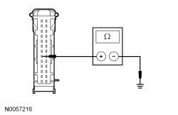
Is the resistance less than 5 ohms?
Yes
GO to A5.
No
REPAIR circuit GD133 (BK) for an open. TEST the system for normal operation.
A5 CHECK FOR CORRECT IC (Instrument Cluster) OPERATION
- Disconnect all the IC (Instrument Cluster) connectors.
- Check for:
- corrosion
- damaged pins
- pushed-out pins
- Connect all the IC (Instrument Cluster) connectors and make sure they seat correctly.
- Operate the system and verify the concern is still present.
Is the concern still present?
Yes
INSTALL a new IC (Instrument Cluster). REFER to Instrument Cluster (IC) . TEST the system for normal operation.
No
The system is operating correctly at this time. The concern may have been caused by a loose or corroded connector.