Pinpoint Test F: One Or More Switch Illumination Is Inoperative
Instrument Cluster and Panel Illumination
Pinpoint Test F: One Or More Switch Illumination Is Inoperative
Refer to Wiring Diagram Set 71, Cluster and Panel Illumination for schematic and connector information Electrical Diagrams.
Normal Operation - Dimmable Lighting
The Smart Junction Box (SJB) sends a pulse-width modulated voltage to the dimmable components.
Fixed Lighting - Expedition
When the accessory delay relay energizes, voltage is supplied to the door lock control switches.
This pinpoint test is intended to diagnose the following:
- Wiring, terminals or connectors
- Adjustable pedal switch
- Ashtray receptacle (Navigator)
- Auxiliary climate control assembly
- Clock (Navigator)
- Door lock control switches
- Floor shifter
- Four-Wheel Drive (4WD) mode select switch
- Headlamp switch
- Message center switch
- Overhead console
- Power liftgate/traction control/hazard switch
- Window control switch(es) (Navigator)
- SJB (Smart Junction Box)
PINPOINT TEST F : ONE OR MORE SWITCH ILLUMINATION IS INOPERATIVE
NOTICE: Use the correct probe adapter(s) when making measurements. Failure to use the correct probe adapter(s) may damage the connector.
F1 CHECK THE RECORDED RESULTS FROM BOTH CONTINUOUS AND ON-DEMAND SELF-TESTS
- Check for recorded DTCs from the continuous and on-demand self-tests.
Are any DTCs present?
Yes
REFER to DTC Charts. Instrument Cluster and Panel Illumination
No
If an individual component is inoperative, GO to F2.
If both the door lock control switches are inoperative for Expedition, GO to F4.
F2 CHECK FOR VOLTAGE TO THE ILLUMINATED COMPONENT
- Ignition OFF.
- Disconnect: Inoperative Illuminated Component.
- Ignition ON.
- Place the headlamp switch to the PARKING LAMPS ON position.
- Rotate the instrument panel dimmer switch to the full illumination position.
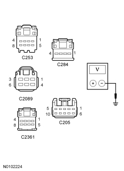
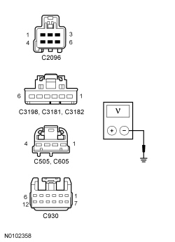
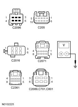
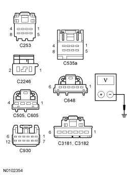
- Measure the voltage between the inoperative illuminated component, harness side and ground as follows:
Expedition
Component Connector-Pin Circuit Message center switch C253-1 VLN18 (BU/WH) Adjustable pedal switch C2089-3 VLN18 (BU/WH) Power liftgate/traction control/hazard switch C2361-1 VLN18 (BU/WH) 4WD (Four-Wheel Drive) mode select switch C284-4 VLN18 (BU/WH) Headlamp switch C205-2 VLN18 (BU/WH)
Expedition (Continued)
Component Connector-Pin Circuit Floor shifter C2096-3 VLN18 (BU/WH) Auxiliary climate control assembly C3198-1 VLN18 (BU/WH) LH door lock control switch C505-2 CBP41 (BU) RH door lock control switch C605-2 CBP41 (BU) Overhead console C930-2 VLN18 (BU/WH) LH rear heated seat switch C3181-5 VLN18 (BU/WH) RH rear heated seat switch C3182-5 VLN18 (BU/WH)
Navigator
Component Connector-Pin Circuit Floor shifter C2096-3 VLN04 (VT/GY) Clock C2016-2 VLN04 (VT/GY) Power liftgate/traction control/hazard switch C2361-1 VLN04 (VT/GY) Headlamp switch C205-2 VLN04 (VT/GY) 4WD (Four-Wheel Drive) mode select switch C2071-1 VLN04 (VT/GY) Adjustable pedal switch C2089-3 VLN04 (VT/GY) LH rear window control switch C701-4 VLN04 (VT/GY) RH rear window control switch C801-4 VLN04 (VT/GY)
Navigator (Continued)
Component Connector-Pin Circuit Message center switch C253-1 VLN04 (VT/GY) Ashtray receptacle C2246-2 VLN04 (VT/GY) LH door lock control switch C505-2 VLN04 (VT/GY) RH door lock control switch C605-2 VLN04 (VT/GY) Overhead console C930-2 VLN18 (BU/WH) LH front window control switch C535A-6 VLN04 (VT/GY) RH front window control switch C648-1 VLN04 (VT/GY) LH rear heated seat switch C3181-5 VLN18 (BU/WH) RH rear heated switch C3182-5 VLN18 (BU/WH)
Is the voltage greater than 10 volts?
Yes
For a window control switch, INSTALL a new window control switch in question. TEST the system for normal operation.
For a door lock control switch, INSTALL a new door lock control switch in question. TEST the system for normal operation.
For a heated seat switch, INSTALL a new heated switch in question. TEST the system for normal operation.
For all other components, GO to F3.
No
REPAIR the voltage supply circuit in question for an open. TEST the system for normal operation
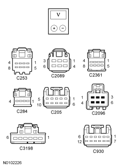
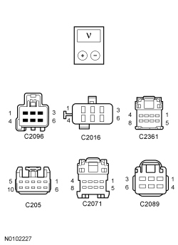
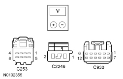
F3 CHECK FOR VOLTAGE TO THE ILLUMINATED COMPONENT USING THE CONNECTOR GROUND
- Measure the voltage between the inoperative illuminated component pins, harness side as follows:
Expedition
Component Connector-Pin/ Circuit Connector-Pin/ Circuit Message center switch C253-1 VLN18 (BU/WH) C253-4 GD138 (BK/WH) Adjustable pedal switch C2089-3 VLN18 (BU/WH) C2089-4 GD138 (BK/WH) Power liftgate/traction control/hazard switch C2361-1 VLN18 (BU/WH) C2361-4 GD138 (BK/WH) 4WD (Four-Wheel Drive) mode select switch C284-4 VLN18 (BU/WH) C284-1 GD138 (BK/WH) Headlamp switch C205-2 VLN18 (BU/WH) C205-1 GD138 (BK/WH) Floor shifter C2096-3 VLN18 (BU/WH) C2096-4 GD143 (BK/VT) Auxiliary climate control assembly C3198-1 VLN18 (BU/WH) C3198-3 GD143 (BK/VT) Overhead console C930-2 VLN18 (BU/WH) C930-12 GD138 (BK/WH)
Navigator
Component Connector-Pin/ Circuit Connector-Pin/ Circuit Floor shifter C2096-3 VLN04 (VT/GY) C2096-4 GD143 (BK/VT) Clock C2016-2 VLN04 (VT/GY) C2016-5 GD138 (BK/WH) Power liftgate/traction control/hazard switch C2361-1 VLN04 (VT/GY) C2361-4 GD138 (BK/WH) Headlamp switch C205-2 VLN04 (VT/GY) C205-1 GD138 (BK/WH) 4WD (Four-Wheel Drive) mode select switch C2071-1 VLN04 (VT/GY) C2071-4 GD138 (BK/WH) Adjustable pedal switch C2089-3 VLN04 (VT/GY) C2089-4 GD138 (BK/WH)
Navigator (Continued)
Component Connector-Pin/ Circuit Connector-Pin/ Circuit Message center switch C253-1 VLN04 (VT/GY) C253-4 GD138 (BK/WH) Ashtray receptacle C2246-2 VLN04 (VT/GY) C2246-1 GD138 (BK/WH) Overhead console C930-2 VLN18 (BU/WH) C930-12 GD138 (BK/WH)
Is the voltage greater than 10 volts?
Yes
INSTALL a new component in question. TEST the system for normal operation.
No
REPAIR the ground circuit in question for an open. TEST the system for normal operation.
F4 BYPASS THE SJB (Smart Junction Box)
- Ignition OFF.
- Disconnect: SJB (Smart Junction Box) C2280D.
- Connect a fused jumper wire between the SJB (Smart Junction Box) C2280D-16, circuit CBP41 (BU), harness side and battery positive.
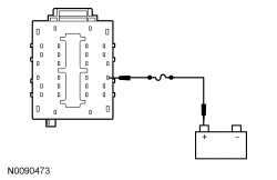
Do the door lock control switches illuminate?
Yes
REMOVE the jumper wire. GO to F5.
No
REMOVE the jumper wire. REPAIR circuit CBP41 (BU) for an open. TEST the system for normal operation.
F5 CHECK FOR CORRECT SJB (Smart Junction Box) OPERATION
- Disconnect all the SJB (Smart Junction Box) connectors.
- Check for:
- corrosion
- damaged pins
- pushed-out pins
- Connect all the SJB (Smart Junction Box) connectors and make sure they seat correctly.
- Operate the system and verify the concern is still present.
Is the concern still present?
Yes
INSTALL a new SJB (Smart Junction Box). TEST the system for normal operation.
No
The system is operating correctly at this time. The concern may have been caused by a loose or corroded connector.