Pinpoint Test E: The Steering Wheel Switch Illumination Is Inoperative
Instrument Cluster and Panel Illumination
Pinpoint Test E: The Steering Wheel Switch Illumination Is Inoperative
Refer to Wiring Diagram Set 71, Cluster and Panel Illumination for schematic and connector information Electrical Diagrams.
Normal Operation
The Smart Junction Box (SJB) sends a pulse-width modulated voltage to the steering wheel. The voltage passes through the clockspring to the steering wheel harness and on to the steering wheel switches.
This pinpoint test is intended to diagnose the following:
- Wiring, terminals or connectors
- Steering wheel switch(es)
- Steering wheel harness
- Clockspring
PINPOINT TEST E : THE STEERING WHEEL SWITCH ILLUMINATION IS INOPERATIVE
NOTICE: Use the correct probe adapter(s) when making measurements. Failure to use the correct probe adapter(s) may damage the connector.
E1 CHECK THE OTHER DIMMABLE LIGHTING SWITCHES
- Ignition OFF.
- Place the headlamp switch in the PARKING LAMPS ON position.
- Rotate the instrument panel dimmer switch to the full illumination position and observe other dimmable switches (hazard lamp switch, headlamp switch for example).
Are all the dimmable switches inoperative?
Yes
GO to Pinpoint Test B. Pinpoint Test B: All Dimmable Switch Illumination Is Inoperative
No
GO to E2.
E2 CHECK FOR VOLTAGE TO THE CLOCKSPRING
- Place the headlamp switch in the OFF position.
- Depower the Supplemental Restraint System (SRS). Refer to Restraints and Safety Systems &/or Air Bag Systems.
- Disconnect: Clockspring C218A.
- Connect: Negative Battery Cable.
- Place the headlamp switch in the PARKING LAMPS ON position.
- Rotate the instrument panel dimmer switch to the full illumination position.
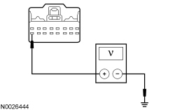
- Measure the voltage between the clockspring C218A-16, circuit VLN04 (VT/GY) (Navigator) or circuit VLN18 (BU/WH) (Expedition), harness side and ground.
Is the voltage greater than 10 volts?
Yes
GO to E3.
No
REPAIR circuit VLN04 (VT/GY) (Navigator) or circuit VLN18 (BU/WH) (Expedition) for an open. REPOWER the SRS (Supplemental Restraint System). REFER to Restraints and Safety Systems &/or Air Bag Systems. TEST the system for normal operation.
E3 CHECK FOR VOLTAGE TO THE CLOCKSPRING USING THE CONNECTOR GROUND
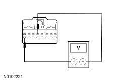
- Measure the voltage between the clockspring C218A-16, circuit VLN04 (VT/GY) (Navigator) or circuit VLN18 (BU/WH) (Expedition), harness side and the clockspring C218A-5, circuit GD133 (BK), harness side.
Is the voltage greater than 10 volts?
Yes
GO to E4.
No
REPAIR circuit GD133 (BK) for an open. REPOWER the SRS (Supplemental Restraint System). REFER to Restraints and Safety Systems &/or Air Bag Systems. TEST the system for normal operation.
E4 CHECK THE CLOCKSPRING FOR AN OPEN
- Remove the driver air bag module.
- Disconnect: Upper Clockspring C218B.
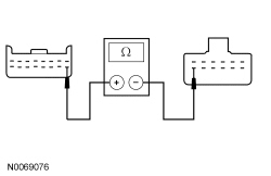
- Measure the resistance between the clockspring C218a pin 16, component side and the upper clockspring C218b pin 7, component side.
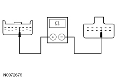
- Measure the resistance between the clockspring C218a pin 5, component side and the upper clockspring C218b pin 4, component side.
Are the resistances less than 5 ohms?
Yes
GO to E5.
No
INSTALL a new clockspring. TEST the system for normal operation.
E5 CHECK THE STEERING WHEEL HARNESS
- Disconnect: Steering Wheel Switches.
- Measure the resistance between the upper clockspring, harness side, and the steering wheel switch(es) as follows:
Expedition
Upper Clockspring Connector-Pin Steering Wheel Switch Connector-Pin Circuit C218B-7 LH steering wheel switch C2366-4RD/BK C218B-7 RH steering wheel switch C2367-6RD/BK C218B-4 LH steering wheel switch C2366-3DG/OG C218B-4 RH steering wheel switch C2367-1DG/OG
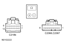
Navigator
Upper Clockspring Connector-Pin Steering Wheel Switch Connector-Pin Circuit C218B-7 LH steering wheel switch C2998-2 RD/BK C218B-7 RH steering wheel switch C2999-1 RD/BK C218B-4 LH steering wheel switch C2998-4 DG/OG C218B-4 RH steering wheel switch C2999-3 DG/OG
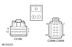
Are the resistances less than 5 ohms?
Yes
INSTALL new steering wheel switch(es). INSTALL the driver air bag module. TEST the system for normal operation.
No
REPAIR or INSTALL a new steering wheel harness. INSTALL the driver air bag module. TEST the system for normal operation.