Pinpoint Test B: All Dimmable Switch Illumination Is Inoperative
Instrument Cluster and Panel Illumination
Pinpoint Test B: All Dimmable Switch Illumination Is Inoperative
Refer to Wiring Diagram Set 71, Cluster and Panel Illumination for schematic and connector information Electrical Diagrams.
NOTE: This symptom also diagnoses the auxiliary climate control assembly for Navigator.
Normal Operation
Based on input received from the instrument panel dimmer switch, the Smart Junction Box (SJB) sends a pulse-width modulated voltage to the hardwired dimmable illumination sources.
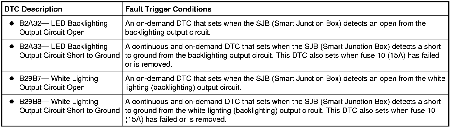
This pinpoint test is intended to diagnose the following:
- Fuse
- Wiring, terminals or connectors
- Auxiliary climate control assembly (Navigator)
- SJB (Smart Junction Box)
PINPOINT TEST B : ALL DIMMABLE SWITCH ILLUMINATION IS INOPERATIVE
NOTICE: Use the correct probe adapter(s) when making measurements. Failure to use the correct probe adapter(s) may damage the connector.
B1 CHECK FOR RECORDED SJB (Smart Junction Box) DTCs FROM THE ON-DEMAND SELF-TEST
- Ignition OFF.
- Use the recorded results from the SJB (Smart Junction Box) self-test.
Is DTC B2A32 or DTC B29B7 recorded?
Yes
GO to B2.
No
VERIFY the SJB (Smart Junction Box) fuse 10 (15A) is OK. If OK, GO to B2.
If not OK, REFER to the Wiring Diagrams to identify the possible causes of the circuit short Electrical Diagrams. After the repair:
If no DTCs are present, TEST the system for normal operation.
If DTC B106E is present, CLEAR the DTCs and REPEAT the self-test (required to enable the backlighting output driver if DTC B106E is present). TEST the system for normal operation.
If DTC B106F is present, INSTALL a new SJB (Smart Junction Box). TEST the system for normal operation.
B2 BYPASS THE SJB (Smart Junction Box)
NOTE: If the jumper wire fails, refer to the Wiring Diagrams to identify the possible causes of the circuit short Electrical Diagrams. After the repair:
If no DTCs are present, test the system for normal operation.
If DTC B106E is present, Clear the DTCs and repeat the self-test (required to enable the courtesy lamp output driver if DTC B106E is present). Test the system for normal operation.
If DTC B106F is present, install a new SJB (Smart Junction Box). Test the system for normal operation.
- Disconnect: SJB (Smart Junction Box) C2280B.
- For DTC B2A32 or DTC B2A33, connect a fused jumper wire between the SJB (Smart Junction Box) C2280B-39, circuit VLN18 (BU/WH) and battery positive.
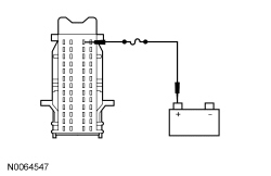
- For DTC B29B7 or DTC B29B8, connect a fused jumper wire between the SJB (Smart Junction Box) C2280B-52, circuit VLN04 (VT/GY) and battery positive.

Do(es) the backlighting component(s) illuminate?
Yes
REMOVE the jumper wire. GO to B5.
No
For Navigator, if the auxiliary climate control is inoperative, REMOVE the jumper wire. GO to B3.
For all others, REMOVE the jumper wire. REPAIR circuit VLN18 (BU/WH) or circuit VLN04 (VT/GY) for an open. CLEAR the DTCs. REPEAT the self-test.
B3 CHECK FOR VOLTAGE TO THE AUXILIARY CLIMATE CONTROL MODULE
- Connect: SJB (Smart Junction Box) C2280B.
- Disconnect: Auxiliary Climate Control Assembly C3198.
- Place the headlamp switch in the PARKING LAMPS ON position.
- Rotate the instrument panel dimmer switch to the full illumination position.
- Measure the voltage between the auxiliary climate control assembly C3198-1, circuit VLN18 (BU/WH), harness side and ground.

Is the voltage greater than 10 volts?
Yes
GO to B4.
No
REPAIR the circuit. CLEAR the DTCs. REPEAT the self-test.
B4 CHECK FOR VOLTAGE TO THE AUXILIARY CLIMATE CONTROL MODULE USING THE CONNECTOR GROUND
- Measure the voltage between the auxiliary climate control assembly C3198-1, circuit VLN18 (BU/WH), harness side and the auxiliary climate control assembly C3198-3, circuit GD143 (BK/VT), harness side.

Is the voltage greater than 10 volts?
Yes
INSTALL a new auxiliary climate control assembly. CLEAR the DTCs. REPEAT the self-test.
No
REPAIR circuit GD143 (BK/VT) for an open. CLEAR the DTCs. REPEAT the self-test.
B5 CHECK FOR CORRECT SJB (Smart Junction Box) OPERATION
- Disconnect all the SJB (Smart Junction Box) connectors.
- Check for:
- corrosion
- damaged pins
- pushed-out pins
- Connect all the SJB (Smart Junction Box) connectors and make sure they seat correctly.
- Operate the system and verify the concern is still present.
Is the concern still present?
Yes
INSTALL a new SJB (Smart Junction Box). TEST the system for normal operation.
No
The system is operating correctly at this time. The concern may have been caused by a loose or corroded connector. RUN the on-demand self-test (required to clear certain DTCs). CORRECT any unresolved DTCs. CLEAR all DTCs. TEST the system for normal operation.