Pinpoint Test D: No Power In Start - Non-Hybrid
- D1 CHECK FOR VOLTAGE TO THE BJB
- Disconnect: BJB OTIS Diode.
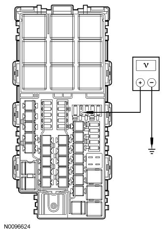
- With the ignition in the START position, measure the voltage between BJB OTIS diode, circuit CDC35 (BU/WH), input side and ground.
 Courtesy of FORD MOTOR CO.
- Is the voltage greater than 10 volts?
- Yes:
GO to D5.
- No:
GO to D2.
- D2 CHECK THE IGNITION START CIRCUIT FOR AN OPEN
- Ignition OFF.
- Disconnect: Ignition Switch C250.
- Measure the resistance between BJB OTIS diode, circuit CDC35 (BU/WH), input side and ignition switch C250-7, circuit CDC35 (BU/WH), harness side.
 Courtesy of FORD MOTOR CO.
- Is the resistance less than 5 ohms?
- Yes:
GO to D3.
- No:
REPAIR circuit CDC35 (BU/WH). TEST the system for normal operation.
- D3 CHECK THE IGNITION START CIRCUIT FOR A SHORT TO GROUND
- Measure the resistance between ignition switch C250-7, circuit CDC35 (BU/WH), harness side and ground.
 Courtesy of FORD MOTOR CO.
- Is the resistance greater than 10, 000 ohms?
- Yes:
GO to D10.
- No:
GO to D4.
- D4 ISOLATE THE PCM FOR A SHORT TO GROUND
- Disconnect: PCM C175B.
- Measure the resistance between ignition switch C250-7, circuit CDC35 (BU/WH), harness side and ground.
Courtesy of FORD MOTOR CO.
- Is the resistance greater than 10, 000 ohms?
- Yes:
GO to D12.
- No:
REPAIR circuit CDC35 (BU/WH). TEST the system for normal operation.
- D5 CHECK THE OTIS DIODE
- Test the OTIS diode.
- Is the OTIS diode OK?
- Yes:
GO to D6.
- No:
INSTALL a new OTIS diode. TEST the system for normal operation.
- D6 CHECK FOR START CIRCUIT VOLTAGE AT THE PCM
- Ignition OFF.
- Connect: BJB OTIS Diode.
- Disconnect: PCM C175B.
- With the ignition in the START position, measure the voltage between ground and:
- 2.5L and 3.0L:
PCM C175B-16, circuit CDC35 (BU/WH), harness side.
- 3.5L:
PCM C175B-10, circuit CDC35 (BU/WH), harness side.
 Courtesy of FORD MOTOR CO.
- Is the voltage greater than 10 volts?
- Yes:
GO to D7.
- No:
REPAIR circuit CDC35 (BU/WH). TEST the system for normal operation.
- D7 CHECK FOR START CIRCUIT VOLTAGE AT THE STARTER RELAY
- Disconnect: BJB Starter Relay.
- With the ignition in the START position, measure the voltage between BJB starter relay socket 86, circuit CE336 (GN/WH), harness side and ground.
 Courtesy of FORD MOTOR CO.
- Is the voltage greater than 10 volts?
- Yes:
GO to D8.
- No:
REPAIR circuit CE336 (GN/WH). TEST the system for normal operation.
- D8 CHECK FOR START CIRCUIT VOLTAGE AT THE PCM
- With the ignition in the START position, measure the voltage between ground and:
- 2.5L and 3.0L:
PCM C175B-37, circuit CE336 (GN/WH), harness side.
- 3.5L:
PCM C175B-19, circuit CE336 (GN/WH), harness side.
 Courtesy of FORD MOTOR CO.
- Is the voltage greater than 10 volts?
- Yes:
GO to D9.
- No:
REPAIR circuit CE336 (GN/WH). TEST the system for normal operation.
- D9 CHECK FOR VOLTAGE TO THE SJB
- Ignition OFF.
- Disconnect: SJB C2280B.
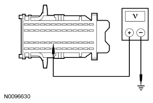
- With the ignition in the START position, measure the voltage between SJB C2280B-32, circuit CE336 (GN/WH), harness side and ground.
 Courtesy of FORD MOTOR CO.
- Is the voltage greater than 10 volts?
- Yes:
GO to D11.
- No:
REPAIR circuit CE336 (GN/WH). TEST the system for normal operation.
- D10 CHECK THE IGNITION SWITCH
- Carry out the Ignition Switch component test. Refer to OEM COMPONENT TESTING (EXCEPT HYBRID)
, or OEM COMPONENT TESTING (HYBRID)
for component testing.
- Did the ignition switch pass the component test?
- Yes:
The system is operating correctly at this time. Concern may have been caused by a loose or corroded connector. TEST the system for normal operation.
- No:
INSTALL a new ignition switch. REFER to IGNITION SWITCH in this information. TEST the system for normal operation.
- D11 CHECK FOR CORRECT SJB OPERATION
- Disconnect: All SJB connectors.
- Check all SJB connectors for:
- corrosion.
- pushed-out pins.
- spread terminals.
- Connect: All SJB connectors making sure that all connectors are seated correctly.
- Operate the system and verify the concern is still present.
- Is the concern still present?
- Yes:
INSTALL a new SJB. REFER to
MULTIFUNCTION ELECTRONIC MODULES
. TEST the system for normal operation.
- No:
The system is operating correctly at this time. Concern may have been caused by a loose or corroded connector.
- D12 CHECK FOR CORRECT PCM OPERATION
- Disconnect: All PCM connectors.
- Check all PCM connectors for:
- corrosion.
- pushed-out pins.
- spread terminals.
- Connect: All PCM connectors making sure that all connectors are seated correctly.
- Operate the system and verify the concern is still present.
- Is the concern still present?