Pinpoint Test Al: The Key-In-Ignition Warning Chime Is Inoperative
- AL1 CHECK THE SAFETY BELT WARNING CHIME OPERATION
- Ignition OFF.
- Ignition ON.
- Monitor the safety belt warning chime when the ignition switch is transitioned from OFF to RUN for 6 seconds.
- Does the safety belt warning chime operate for approximately 6 seconds?
- AL2 CHECK THE INTERIOR LAMPS OPERATION
- Open and close the driver door.
- Observe the interior lamps.
- Do the interior lamps operate correctly from the driver door?
- AL3 RETRIEVE THE RECORDED DTCs FROM THE BCM SELF-TEST
- Check the recorded DTCs from the BCM self-test.
- Is DTC B10F1:14 present?
- Yes
: GO to AL4.
- No
: GO to AL6.
- AL4 CHECK THE KEY-IN-IGNITION INPUT CIRCUIT FOR VOLTAGE
- Ignition OFF.
- Insert the key into the ignition cylinder.
- Disconnect: BCM C2280B.
- Measure the voltage between the BCM C2280B-34, circuit CDC30 (BU/GY), harness side and ground.
- Is the voltage greater than 10 volts?
- Yes
: GO to AL6.
- No
: GO to AL5.
- AL5 CHECK THE IGNITION SWITCH
- Ignition OFF.
- Disconnect: Ignition Switch C250.
- Carry out the ignition switch component test. Refer to appropriate SYSTEMS WIRING DIAGRAMS article.
- Diagrams OEM COMPONENT TESTING
.
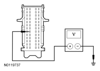 Courtesy of FORD MOTOR CO.
- Is the ignition switch OK?
- Yes
: REPAIR circuit CDC30 (BU/GY) for an open. CLEAR the DTCs. REPEAT the self-test.
- No
: INSTALL a new ignition switch. REFER to
STEERING COLUMN SWITCHES
. CLEAR the DTCs. REPEAT the self-test.
- AL6 CHECK FOR CORRECT BCM OPERATION
- Disconnect all the BCM connectors.
- Check for:
- corrosion
- damaged pins
- pushed-out pins
- Connect all the BCM connectors and make sure they seat correctly.
- Operate the system and verify the concern is still present.
- Is the concern still present?
- Yes
: INSTALL a new BCM. REFER to
MULTIFUNCTION ELECTRONIC MODULES
. TEST the system for normal operation.
- No
: The system is operating correctly at this time. The concern may have been caused by a loose or corroded connector.