Pinpoint Test Ah: The Key-In-Ignition Warning Chime Is Inoperative
- AH1 CARRY OUT THE CHIME FUNCTION ACTIVE COMMAND
- Ignition ON.
- Enter the following diagnostic mode on the scan tool: IPC DataLogger.
- Select the IPC chime command (SOUNDER_OUT).
- Scroll through the chimes to select Key-In-Ign chime.
- Does the key-in-ignition chime operate?
- Yes
: GO to AH2.
- No
: INSTALL a new IPC. REFER to INSTRUMENT PANEL CLUSTER (IPC) . TEST the system for normal operation.
- AH2 CHECK THE DOOR AJAR MESSAGE CENTER WARNING INDICATOR OPERATION
- Ignition ON.
- Open then close the LH front door while observing the door ajar message center warning indicator.
- Does the door ajar message center warning indicator operate correctly?
- Yes
: GO to AH3.
- No
: GO to PINPOINT TEST X .
- AH3 RETRIEVE THE RECORDED DTCs FROM THE SJB SELF-TEST
- Check for recorded DTCs from the SJB self-test.
- Is DTC B1352 present?
- Yes
: GO to AH4.
- No
: INSTALL a new SJB. REFER to
MULTIFUNCTION ELECTRONIC MODULES
. TEST the system for normal operation.
- AH4 CHECK THE SJB KEY-IN-IGNITION INPUT CIRCUIT FOR VOLTAGE
- Ignition OFF.
- Disconnect: SJB C2280B.
- Ignition In ACC.
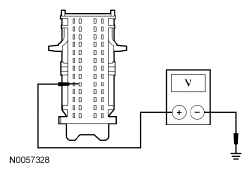
- Measure the voltage between the SJB C2280B-35, circuit CDC30 (BU/GY), harness side and ground.
 Courtesy of FORD MOTOR CO.
- Is the voltage greater than 10 volts?
- Yes
: GO to AH7.
- No
: GO to AH5.
- AH5 CHECK THE SJB KEY-IN-IGNITION INPUT CIRCUIT FOR AN OPEN BETWEEN THE SJB AND THE RFA MODULE
- Ignition OFF.
- Disconnect: RFA Module C2153D.
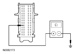
- Measure the resistance between the SJB C2280B-35, circuit CDC30 (BU/GY), harness side and the RFA module C2153D-1, circuit CDC30 (BU/GY), harness side.
 Courtesy of FORD MOTOR CO.
- Is the resistance less then 5 ohms?
- Yes
: GO to AH6.
- No
: REPAIR circuit CDC30 (BU/GY) for an open. CLEAR the DTCs. REPEAT the self-test.
- AH6 CHECK THE SJB KEY-IN-IGNITION INPUT CIRCUIT FOR A SHORT TO GROUND
- Measure the resistance between the SJB C2280B-35, circuit CDC30 (BU/GY), harness side and ground.
 Courtesy of FORD MOTOR CO.
- Is the resistance greater than 10, 000 ohms?
- Yes
: GO to AH8.
- No
: REPAIR circuit CDC30 (BU/GY) for a short to ground. CLEAR the DTCs. REPEAT the self-test.
- AH7 CHECK FOR CORRECT SJB OPERATION
- Disconnect all the SJB connectors.
- Check for:
- corrosion
- damaged pins
- pushed-out pins
- Connect all the SJB connectors and make sure they seat correctly.
- Operate the system and verify the concern is still present.
- Is the concern still present?
- Yes
: INSTALL a new SJB. REFER to
MULTIFUNCTION ELECTRONIC MODULES
. TEST the system for normal operation.
- No
: The system is operating correctly at this time. The concern may have been caused by a loose or corroded connector.
- AH8 CHECK FOR CORRECT RFA MODULE OPERATION
- Disconnect all the RFA module connectors.
- Check for:
- corrosion
- damaged pins
- pushed-out pins
- Connect all the RFA module connectors and make sure they seat correctly.
- Operate the system and verify the concern is still present.
- Is the concern still present?
- Yes
: INSTALL a new RFA module. REFER to
MULTIFUNCTION ELECTRONIC MODULES
. TEST the system for normal operation.
- No
: The system is operating correctly at this time. The concern may have been caused by a loose or corroded connector.