Brake Booster
 Courtesy of FORD MOTOR CO.
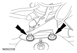
- Remove the 2 nuts and position the vapor management valve (VMV) and bracket assembly aside.
- To install, tighten to 28 Nm (21 lb-ft).
 Courtesy of FORD MOTOR CO.
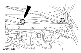
- Remove the 2 nuts and the 2 windshield wiper pivot arms.
- To install, tighten to 25 Nm (18 lb-ft).
 Courtesy of FORD MOTOR CO.
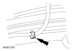
- Disconnect the windshield washer hose.
 Courtesy of FORD MOTOR CO.
- Remove the cowl panel grille.
- Remove the cowl panel grille pin-type retainers.
- Remove the cowl panel grille rubber trim.
- Remove the cowl panel grille.
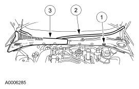 Courtesy of FORD MOTOR CO.
- Remove the 7 bolts and the strut tower support brace.
- To install, tighten to 20 Nm (15 lb-ft)
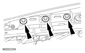 Courtesy of FORD MOTOR CO.
- Disconnect the degas bottle return hose.
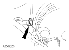 Courtesy of FORD MOTOR CO.
- Remove the 2 degas bottle bolts and position the degas bottle aside.
- To install, tighten to 15 Nm (11 lb-ft).
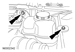 Courtesy of FORD MOTOR CO.
- Remove the brake master cylinder. For additional information, refer to HYDRAULIC BRAKE ACTUATION
.
- Disconnect the brake booster vacuum hose from the vacuum check valve.
- Remove the speed control deactivation switch. For additional information, refer to SPEED CONTROL
.
- Remove the stoplamp switch. For additional information, refer to EXTERIOR LIGHTING
.
- Remove the 2 screws and the switch bracket.
- Remove and discard the 4 brake booster-to-brake pedal bracket nuts.
- To install, tighten to 27 Nm (20 lb-ft).
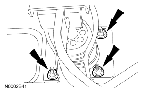 Courtesy of FORD MOTOR CO.
- Disconnect the brake pedal pin from the brake booster input shaft.
- Remove the redundant self-locking clip.
- Disconnect the booster rod from the brake pedal.
- Remove the brake booster from the vehicle.
- To install, reverse the removal procedure.