Pinpoint Test B: The Instrument Cluster Illumination Is Inoperative
- B1 MONITOR THE INSTRUMENT PANEL DIMMER SWITCH INPUT TO THE INSTRUMENT CLUSTER
- Carry out the instrument cluster self-test. Refer to INSTRUMENT CLUSTER
.
- Advance the self-diagnostic mode until PWM DIM INPUT is displayed on the message center (Expedition/Navigator with message center) or rhO is displayed on the odometer (Expedition with base cluster).
- Turn the headlamp switch to the parking lamps ON position.
- Rotate the instrument panel dimmer switch from the full dim to the full illumination positions while observing the odometer display.
- Does the value displayed vary from 1 in the full dim position to 22 in the full illumination position?
- Yes
: INSTALL a new instrument cluster. REFER to INSTRUMENT CLUSTER
. TEST the system for normal operation.
- No
: GO to B2.
- B2 CHECK THE VOLTAGE TO THE INSTRUMENT CLUSTER ILLUMINATION
- Key in OFF position.
- Turn the headlamp switch off.
- Disconnect: Instrument Cluster C220a.
- Turn the headlamp switch to the parking lamps ON position.
- Rotate the instrument panel dimmer switch to the full illumination position.
- For Expedition, measure the voltage between the instrument cluster C220a pin 6, circuit 19 (LB/RD), harness side and ground.
- For Navigator, measure the voltage between the instrument cluster C220a pin 6, circuit 505 (GY/YE), harness side and ground.
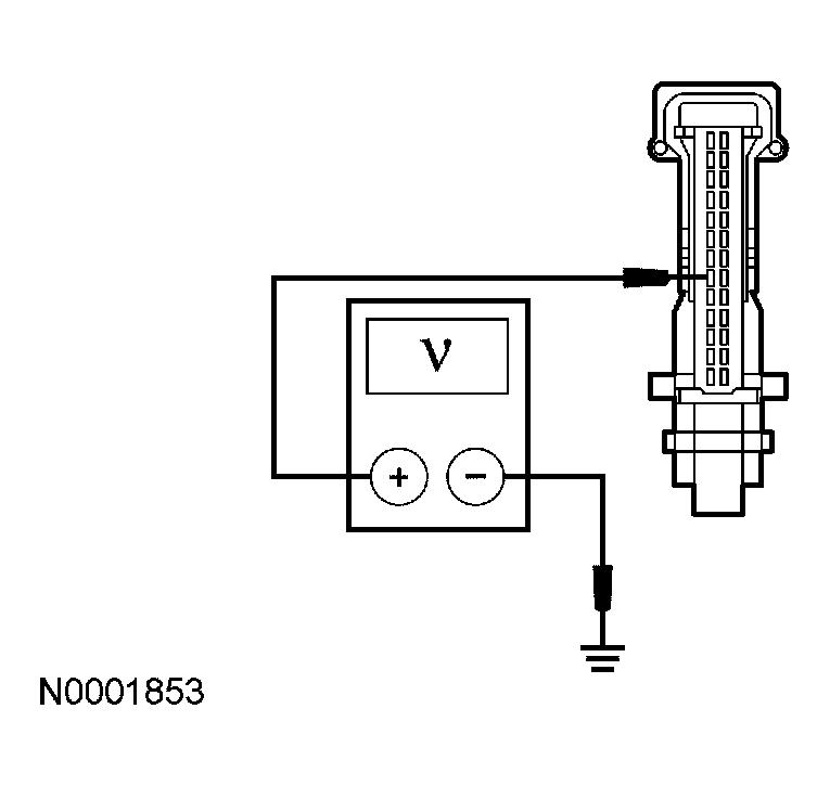 Courtesy of FORD MOTOR CO.
- Is the voltage greater than 10 volts?
- Yes
: GO to B3.
- No
: REPAIR the circuit in question. TEST the system for normal operation.
- B3 CHECK THE GROUND CIRCUIT TO THE INSTRUMENT CLUSTER
- Turn the headlamp switch off.
- For Expedition, measure the resistance between the instrument cluster C220a pin 10, circuit 57 (BK), harness side and ground.
- For Navigator, measure the resistance between the instrument cluster C220a pin 9, and pin 22, circuit 676 (PK/OG), harness side and ground.
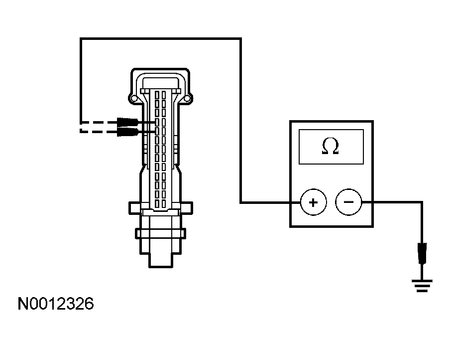 Courtesy of FORD MOTOR CO.
- Is the resistance less than 5 ohms?
- Yes
: GO to B4.
- No
: REPAIR the circuit. TEST the system for normal operation.
- B4 CHECK FOR CORRECT INSTRUMENT CLUSTER OPERATION
- Disconnect all the instrument cluster connectors.
- Check for:
- corrosion
- pushed-out pins
- Connect all the instrument cluster connectors and make sure they seat correctly.
- Operate the system and verify the concern is still present.
- Is the concern still present?
- Yes
: INSTALL a new instrument cluster. REFER to INSTRUMENT CLUSTER
. TEST the system for normal operation.
- No
: The system is operating correctly at this time. The concern may have been caused by a loose or corroded connector.