Test At: All LEDS Or Incandescent Lights Always On
- Turn ignition switch to RUN position. If only power window, power door lock and memory switches are illuminated, go to next step. If all LEDs and incandescent lights are always illuminated, perform TEST AU: ALL LEDS & INCANDESCENT LIGHTS ALWAYS ON
. If only emergency message switch, seat heater switches, cigarette lighter, traction control switch, transmission sift lever, instrument cluster, message center steering wheel switches (if equipped), main light switch, panel dimmer switch, mirror switch and message center switch lights are illuminated, go to step 7
.
- Turn ignition switch to LOCK position. Disconnect Front Electronic Module (FEM) 26-pin harness connector C201e. FEM is located behind driver's side kick panel. See Figure
. Turn ignition switch to RUN position. If power window, power door lock and memory switches are illuminated, go to next step. If power window, power door lock and memory switches do not illuminate, replace FEM.
- Turn ignition switch to LOCK position. Disconnect Interior Auxiliary Junction Box (IAJB) 16-pin harness connector C283a. IAJB is located, behind driver's side kick panel. Turn ignition switch to RUN position. If any switches are still illuminated, go to next step. If no switches are illuminated, repair short to voltage in Blue wire between IAJB and FEM.
- Turn ignition switch to LOCK position. Disconnect Interior Auxiliary Junction Box (IAJB) harness connector C283b. Turn ignition switch to RUN position. If switches on passenger's side of vehicle are still illuminated, go to next step. If switches on driver's door are still illuminated, repair short to voltage in Orange/Yellow wire between IAJB and switches on driver's door. If left rear power window switch is still illuminated, repair short to voltage in Orange wire between IAJB and left rear power window switch. If no switches are illuminated, replace IAJB.
- Turn ignition switch to LOCK position. Disconnect Central Junction Box (CJB) 26-pin harness connector C270d. CJB is located, behind passenger's side kick panel. Turn ignition switch to RUN position. If no switches are illuminated, go to next step. If right rear power window switch is still illuminated, repair short to voltage in Orange/Black wire between CJB and right rear power window switch. If passenger's door switches are still illuminated, repair short to voltage in Orange/Blue wire between CJB and passenger's door switches.
- Measure voltage between ground and CJB harness connector C270d terminal No. 24 (Orange/Blue wire). See Fig 1
. If voltage exists, repair short to voltage in Orange/Blue wire between IAJB and CJB. If voltage does not exist, replace CJB.
- Turn ignition switch to LOCK position. Disconnect Front Electronic Module (FEM) 20-pin harness connector C201f. FEM is located behind driver's side kick panel. See Figure
. Turn ignition switch to RUN position. If instrument cluster, message center steering wheel switches (if equipped), main light switch, panel dimmer switch, mirror switch and message center switch lights are still illuminated, go to next step. If instrument cluster, message center steering wheel switches (if equipped), main light switch, panel dimmer switch, mirror switch and message center switch lights are not still illuminated, replace FEM.
- Turn ignition switch to LOCK position. Disconnect Interior Auxiliary Junction Box (IAJB) 16-pin harness connectors C283a and C283d. IAJB is located, behind driver's side kick panel. Turn ignition switch to RUN position. If no switches are illuminated, go to next step. If emergency message switch, seat heater switches, cigarette lighter, traction control switch and transmission sift lever lights are still illuminated, repair short to voltage in wiring as necessary. See WIRING DIAGRAMS
. If instrument cluster, message center steering wheel switches (if equipped), main light switch, panel dimmer switch, mirror switch and message center switch lights are still illuminated, go to step 10
.
- Measure voltage between ground and IAJB 16-pin harness connector C283a terminal No. 13 (Blue/Red wire). See Figure
. If voltage exists, repair short to voltage in Blue/Red wire between IAJB and FEM. If voltage does not exist, replace IAJB.
- Turn ignition switch to LOCK position. Disconnect joint connector No. 3 22-pin harness connector C224. Joint connector No. 3 is located, behind left side of instrument panel. Turn ignition switch to RUN position. If no switches are illuminated, go to next step. If any switches are still illuminated, repair short to voltage in wiring as necessary.
- Measure voltage between ground and joint connector No. 3 harness connector C224 terminal No. 13 (Blue wire). See Figure
. If voltage exists, repair short to voltage in Blue wire between IAJB and joint connector No. 3. If voltage does not exist, replace joint connector No. 3.
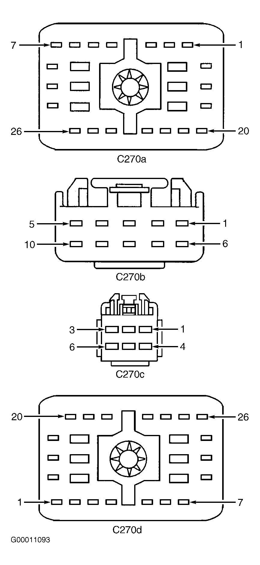 Courtesy of FORD MOTOR CO.