Test B: No Communication With Front Electronic Module
- Turn ignition switch to LOCK position. Disconnect Front Electronic Module (FEM) harness connectors C201c and C201f. Turn ignition switch to RUN position. Measure voltage at terminal No. 6 (Orange/Green wire) at FEM harness connector C201c. See Fig 1
. Measure voltage at terminal No. 1 (Orange/Yellow wire) at FEM harness connector C201f. If battery voltage exists at both terminals, go to next step. If battery voltage does not exist at both terminals, repair power distribution circuit as necessary. See POWER DISTRIBUTION article in WIRING DIAGRAMS.
- Turn ignition switch to LOCK position. Disconnect FEM harness connector C201a. Measure resistance between ground and terminal No. 12 (Black/Red wire) at FEM harness connector C201c. Measure resistance between ground and terminals No. 11, 13, 14 and 15 (all Black/Red wires) at FEM harness connector C201a. If all resistances are 5 ohms or less, diagnose module communications concern. See MODULE COMMUNICATIONS NETWORK - LS
article. If any resistance is greater than 5 ohms, repair open in appropriate wire between FEM and ground.
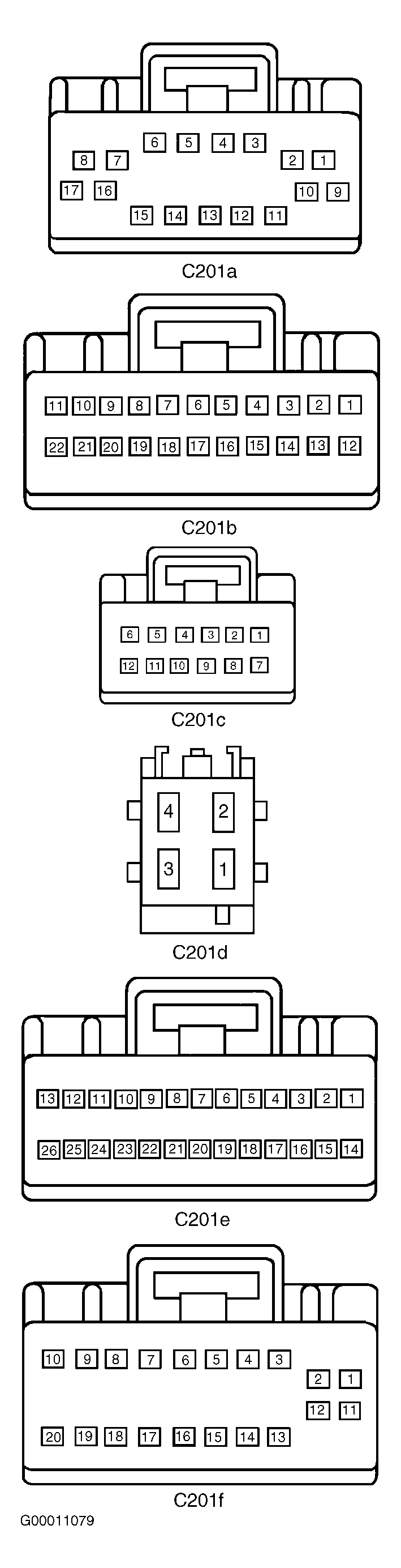 Courtesy of FORD MOTOR CO.